


Concord Ultra 8
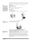
After determining panel location, run all necessary wires to that location using the guidelines in
Table 4.
Mounting the Panel
Use the following procedure to mount the panel to the wall or wall studs.
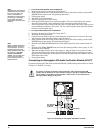
Make sure you are free of static electricity whenever you work on the panel with the cover
open. To discharge any static, first touch the metal panel chassis, then stay in contact with
the chassis when touching the circuit board. Using an approved grounding strap is recom-
mended.
¾To mount the panel:
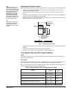
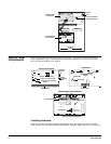
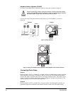
1. Open the panel door and remove the necessary wiring knockouts (see Figure 2). Be careful
not to damage the circuit board.
2. Feed all wires through wiring knockouts and place the panel in position against the wall.
3. Level the panel and mark the top right and bottom mounting holes (see Figure 2). You will
be unable to mark the top left mounting hole.
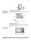
4. Make a level mark 10 inches to the left of the top right mounting mark. This will be the posi-
tion of the top left mounting screw.
5. Install anchors where studs are not present.
Note
Insert the top left screw as
far as possible into the wall,
leaving enough room to
hang the panel on it. After
the panel is hung, you will
be unable to tighten this
screw.
6. Partially insert screws into the two top mounting hole locations, then hang the panel on the
two screws.
7. Recheck for level, insert the two lower screws, and tighten the top right and lower mounting
screws.
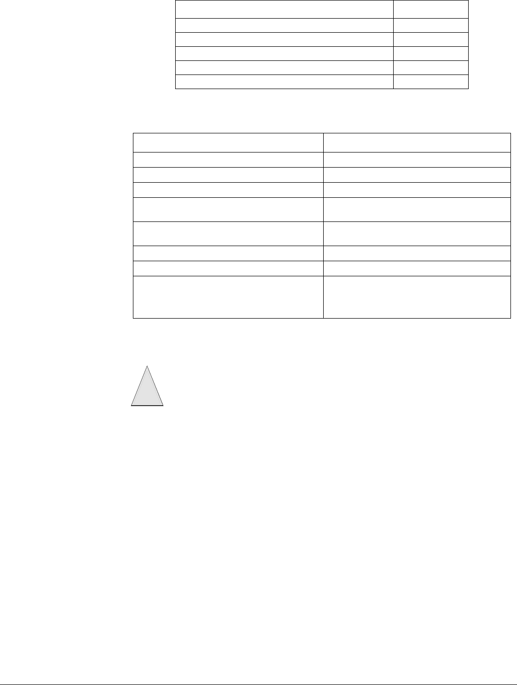
SuperBus 2000 Automation Module 30 mA
SuperBus 2000 Transceiver Module 50 mA
SuperBus 2000 Wireless Gateway Module 55 mA
Interrogator 200 10 mA
Interrogator AVM 45 mA
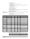
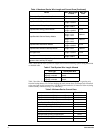
Table 4: Wire Requirements
Device Wire Requirements
AC Power Transformer 2-conductor, 18-gauge, 25 feet max
Earth Ground Single conductor, 16-gauge solid, 25 feet max
Telephone (RJ-31X) 4-conductor
Detection Devices
2- or 4-conductor, 18- to 22-gauge, 300-ohms
max loop resistance including device
Speakers
2-conductor, 22-gauge, 175 feet max
2-conductor, 18-gauge, 440 feet max
SuperBus 2000 Devices 4-conductor, 22- or 18-gauge
Interrogator 200 AVM Power and Microphone 4-conductor, 22-gauge, shielded
2-Wire Smoke Detectors
2-conductor, 22-gauge, 330 feet max
2-conductor, 18-gauge, 830 feet max
(based on 10-ohms max loop resistance plus
a 2k-ohm, end-of-line resistor)
Table 3: Minimum Device Current Draw
Device Min. mA Draw
Caution
!