


Concord Ultra
9
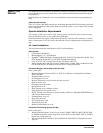
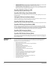
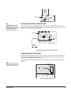
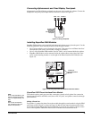
Figure 2. Mounting the Panel
Identify Panel
Components
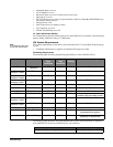
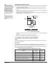
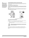
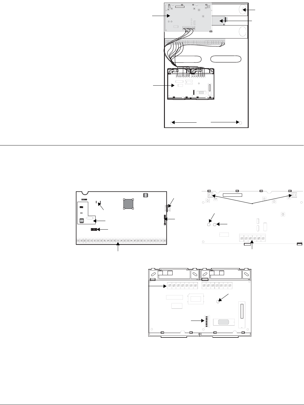
Before installing devices and making wiring connections, familiarize yourself with the main
panel components. Figure 3 shows the three main panel components: the circuit board, trans-
ceiver and phone interface/voice module.
Figure 3. Panel Components
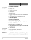
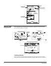
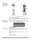
Installing Antennas
Install the antennas (included with panel) through the holes in the panel cabinet and into the
inside terminal of each antenna terminal block on the SuperBus 2000 Transceiver (see Figure 4).
ID: XXXXXXXX
Knockout
Knockout
Mounting
Holes
Mounting
Hole
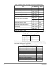
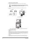
SuperBus 2000
Transceiver
Phone Interface/
Voice Module
Panel Circuit Board
(under Transceiver)
Panel Circuit Board
Power Line Carrier Card
Terminal Strip
Backup Battery Leads
Snapcard
Header
Header
Programming Touchpad
Phone
Supervision
Card
ID : X X X X X XX X
Terminal Strip
Status LED
Power LED
Antenna Terminal
Blocks
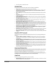
Transceiver
Phone Interface/Voice Module
Terminal Strip
Status LED
DIP Switches