


Concord Ultra
5
• 4 Output SnapCard: Provides four form C relay outputs that can be set up to activate other
signalling devices, based on system events, schedules, or direct control.
• 4Z Input/2 Output Combo SnapCard: Provides three hardwire zone inputs, one two wire
smoke detector loop, and two outputs that can be set up to activate other signalling devices,
based on system events, schedules, or direct control.
SuperBus 2000 8Z Input Module (HIM)
Provides eight additional hardwire zone inputs.
SuperBus 2000 4-Relay Output Module (HOM)
Provides four form C relay outputs that can be set up to activate other signalling devices, based
on system events.
Interrogator 200 Audio Verification Module
Adding this module allows central station operators to listen-in and talk to occupants on the pre-
mises to verify the emergency when an alarm report is received.
SuperBus 2000 Cellular Backup Module
Provides central station communication (cellular transmission) a backup to regular phone line(s).
SuperBus 2000 Energy Saver Module (ESM)
Provides a money-saving and convenient way to monitor and control temperatures. The ESM
uses low- and high-temperature limits to save energy by overriding the existing HVAC thermo-
stat. When the ESM is on, temperature limits determine when the heat or air-conditioning turns
on. When the ESM is off, the HVAC thermostat controls heat and air-conditioning.
SuperBus 2000 Automation Module
Provides a connection to a compatible home automation device.
SuperBus 2000 Wireless Gateway Module
Allows users to control and monitor the status of their system from the alarm.com internet web-
site. A wireless data transceiver on the module provides the link to a wireless 2-way paging net-
work for website access.
Installing the
System
This section describes how to install the system control panel. Before starting the installation,
plan your system layout and programming using the worksheets provided in Appendix A.
Installing the system consists of the following:
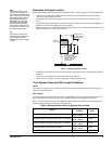
• Determining the Panel Location
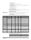
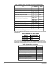
• Determining Total System Power and Wire Length Guidelines
• Mounting the Panel
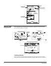
• Identifying Panel Main Components
• Installing the Optional Power Line Carrier Card
• Installing Optional SnapCards
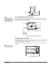
• Connecting Detection Devices to Panel Zone Inputs
• Connecting Speakers
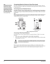
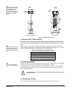
• Connecting Piezo Sirens
• Connecting an Interrogator 200 Audio Verification Module
• Connecting Alphanumeric and Fixed Display Touchpads
• Installing SuperBus 2000 Modules
• Installing an RJ-31X Phone Jack
• Connecting the Phone Line to the Panel with a DB-8 Cord
• Connecting the AC Power Transformer
• Powering Up the Panel