


Concord Ultra 14
(01710) activates the output for status and alarm tones, allowing for a piezo siren connection
without changing the output configuration number. It is typically used for interior siren applica-
tion.
For more information on output configuration numbers, see “Onboard Options Menu”.
Note
Piezo siren connections to
terminal 10 require a 2k
resistor that can be located
at the panel, since it does
not supervise the circuit. If
using an external power
supply instead of panel ter-
minal 4, the supply voltage
must be limited to 9.5 VDC
maximum and the negative
side of the power supply
must be connected to panel
ground (terminal 3).
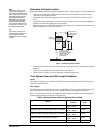
Exterior Sirens
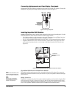
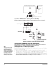
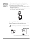
Hardwire Exterior Siren (13-046)
Note
This siren is not UL approved for use as an outdoor sounding device.
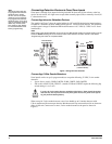
Connect the siren to panel as shown in Figure 11.
Interior Sirens
Interior Piezo Siren (60-278)
Connect the piezo siren to the panel terminals with a 2k-ohm resistor, as shown in Figure 11.
Figure 11. Wiring Sirens
Note
The volume switch settings
inside the siren do not affect
the siren output.
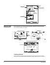
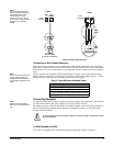
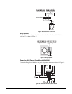
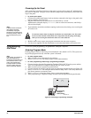
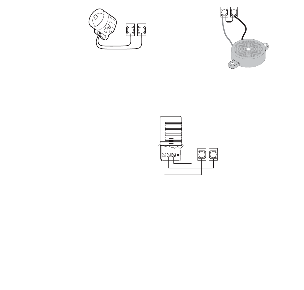
Slim Line Hardwire Interior Siren (60-483-01)
Connect the siren to the panel as shown in Figure 12.
Figure 12. Wiring the Slim Line Hardwire Interior Siren
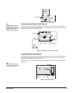
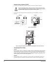
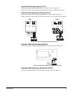
Installing Supervised Wireless Sirens (60-736-95)
Note
Power Line Carrier Card
must be installed for Super-
vised Wireless Sirens to
work.
Supervised Wireless Sirens (SWS) plug directly into electrical outlets and are not wired to the
panel. The panel (when powered by a line carrier power transformer) sends alarm and status mes-
sages to the siren, along the building AC wiring.
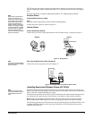
For supervised operation, the siren has a built-in transmitter that, when learned into panel mem-
ory, transmits to the panel receiver if the siren has a low battery or other trouble condition.
Before plugging in Supervised Wireless Sirens, the panel must be powered up and partition
House Codes and the SWS Supervision Code set (in program mode) to the desired settings.
The following procedures describe the basic steps for installing Supervised Wireless Sirens. For
complete installation details, refer to the Supervised Wireless Siren Installation Instructions,
included with each siren.
Panel
Terminals
Black
Red
Red
Black
Panel Terminals
+12V Out 2
+12V Out 1
2k Ohm
Resistor
49-454
49
4
10
Interior
Exterior
Panel
Terminals
Not
Used
+12V
OUT2
4
10