


92
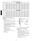
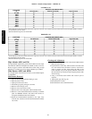
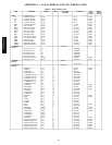
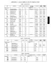
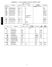
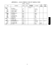
Table 29 – Altitude Compensation* − 48PM16−20
NATURAL GAS
ELEVATION
(ft)
NATURAL GAS ORIFICE SIZE†
Low Heat (D,L) Medium Heat (E,M) High Heat (F,N)
0‐1,999
29 30 29
2,000
29 30 29
3,000
30 31 30
4,000
30 31 30
5,000
30 31 30
6,000
30 31 30
7,000
31 32 31
8,000
31 32 31
9,000
31 32 31
10,000
32 33 32
*As the height above sea level increases, there is less oxygen per cubic foot of air. Therefore, heat input rate should be reduced at higher altitudes. Includes a
4% input reduction per each 1000 ft.
†Orifices available through the local Carrier dealer.
PROPANE GAS
ELEVATION
(ft)
PROPANE GAS ORIFICE SIZE†
Low Heat (D,L) Medium Heat (E,M) High Heat (F,N)
0‐1,999
35 38 35
2,000
36 39 36
3,000
36 39 36
4,000
37 40 37
5,000
37 40 37
6,000
38 41 38
7,000
39 42 39
8,000
40 43 40
9,000
41 44 41
10,000
42 45 42
*As the height above sea level increases, there is less oxygen per cubic foot of air. Therefore, heat input rate should be reduced at higher altitudes. Includes a
4% input reduction per each 1000 ft.
†Orifices available through the local Carrier dealer.
High Altitude (48PG and PM)
For high altitude applications greater than 2,000 ft the heat input
rate should be reduced. The higher the altitude is above sea level,
the less oxygen is in the air. See Table 28 for orifice sizing. A high
altitude kit is available to convert unit for altitudes up to 7,000 ft.
Main Burners (48PG and 48PM)
For all applications, main burners are factory set and should require
no adjustment.
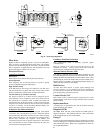
Main Burner Removal
1. Shut off (field-supplied) manual main gas valve.
2. Shut off power to unit.
3. Open gas section access door.
4. Disconnect gas piping from gas valve inlet.
5. Remove wires from gas valve.
6. Remove wires from rollout switch.
7. Remove sensor wire and ignitor cable from IGC board.
8. Remove 2 screws that hold the burner assembly to vestibule
plate. For 48PM16−28 units, also remove the 2 screws se-
curing the manifold bracket to the basepan.
9. Rotate the burner/manifold assembly to the right, away
from the flue extension and lift burner/manifold assembly
out of unit.
Cleaning and Adjustment
1. Remove burner rack from unit as described in Main Burner
Removal section above.
2. Inspect burners, and if dirty, remove burners from rack. The
two outer burners have the flame crossover closed off in
order to prevent gas flow from exiting the sides of the
burner assembly. To prevent ignition problems, make sure
the outer burners are returned to their original position when
done servicing.
3. Using a soft brush, clean burners and crossover port as
required.
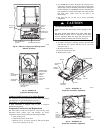
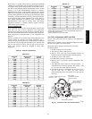
4. Adjust spark gap. (See Fig. 70.)
5. Reinstall burners on rack.
6. Reinstall burner rack as described above.
48/50PG and PM