


13
Heating Test
The heating (HEAT) submenu is used to change output status for
the individual heat stages, gas or electric. The fans (FANS) and
cooling (COOL) service test outputs are reset to OFF for the
heating service test. Indoor and outdoor fans are controlled
normally to maintain proper unit operation. If adaptive fan is
configured, then the indoor fan speed will default to the heating
configuration point (Configuration→A.FAN→FS.HT) when a
stage of heat is turned on. The Reduced Heat Fan Speed (F.SPD)
can only be changed while one stage is running. If more then one
stage is on the actual fan speed will be 100%. F.SPD shows the
reduced speed not actual speed. On single stage units actual fan
speed will be 100% when that stage is turned on. All normal
heating alarms and alerts are functional.
NOTE: Field terminal strip terminal R must be connected to W1
for the heat to operate in service test. Alert number T410 will occur
as a reminder if not done. If the normal unit control mode is
thermostat mode, then remove the R−W1 jumper after completing
service test.
THIRD PARTY CONTROL
Third party controls may interface with the unit ComfortLink
controls through the connections described below. See other
sections of these instructions for more information on the related
unit control and configurations.
Cooling/Heating Control
The thermostat inputs are provided on the field connection terminal
board. The Unit Control Type configuration,
Configuration→UNIT→U.CTL, must be 2 to recognize the
below inputs. Terminal R is the 24vac source for the following:
Y1 = First stage cooling
Y2 = Second stage cooling
W1 = First stage heating
W2 = Second stage heating
G = Indoor fan
Dehumidification Control
On Humidi−MiZer units terminals Humidistat 1 and 2 are
provided on the field connection terminal board. Humidity Switch
configuration, Configuration→UNIT→RH.SW, identifies the
normally open or normally closed status of this input at LOW
humidity. The Humidistat 1 terminal is the input signal and R can
be used as the source.
NOTE: Dehumidification is considered a cooling function in the
software and is only available on Humidi-MiZer equipped units.
Remote Occupancy
The remote occupancy input is provided on the field connection
terminal board (TB1). The Remote Occupancy Switch
configuration, Configuration→UNIT→RM.SW, identifies the
normally open or normally closed status of this input when
unoccupied.
5 = 24 VAC signal input
6 = 24 VAC source for dry contact
Fire Shutdown
The fire shutdown input is provided for unit shutdown in response
to a fire alarm or smoke detector. The Fire Shutdown Switch
configuration, Configuration→UNIT→FS.SW, identifies the
normally open or normally closed status of this input when there is
no fire alarm.
For 48/50 units without Humidi-MiZer system, input at field
connection terminal board (TB1)
Fire Shutdown 1 = 24 VAC source for dry contact
Fire Shutdown 2 = 24 VAC signal input
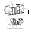
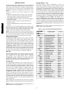
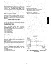
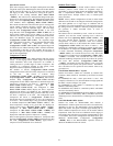
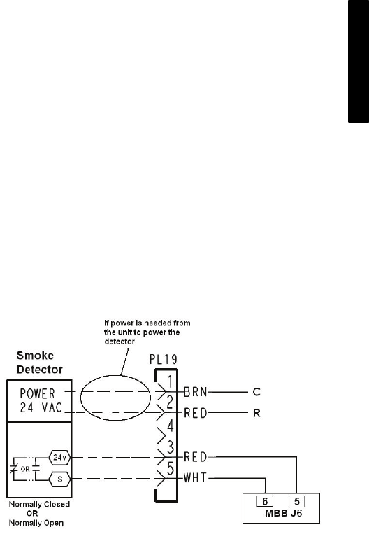
For 50 series units with Humidi-MiZer system, input at wire
harness plug 19 (PL 19). (See Fig. 7.)
PL 19-3 = 24 VAC source for dry contact
PL 19-5 = 24 VAC signal input
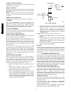
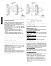
For 48 series units with Humidi-MiZer system, input at wire
harness plug 19 (PL 19). (See Fig. 8.)
PL 19-3 = 24 VAC source for dry contact
PL 19-5 = 24 VAC signal for Fire Shutdown
PL 19-4 = 24 VAC power for indoor fan contactor control
circuit
NOTE: If the indoor fan must be shut down without any delay
upon Fire Shutdown input, then the factory jumper between
PL19-3 and PL19-4 must be replaced with a normally closed
contact when there is no alarm (open with alarm).
The plug PL19 is located in the return air section on
48/50PG03−14 size units and under the control box on and
48/50PM16−28 units.
Alarm Output
The alarm output is provided on the field connection terminal
board (TB1) to indicate a current alarm status. The output will be
24VAC if a current alarm exists.
C = 24 VAC common
X = 24 VAC signal output
C08580
Fig. 7 − 50PG/PM Humidi−MiZert − Third Party Smoke
Detector Wiring
48/50PG and PM