


35
Fan Speed − Reheat2 (FS.RH)
This configuration defines the fan speed used when Hot Gas
Reheat (reheat2) is being requested. Fan speed is based on how
many cooling stages the unit has, how many cooling stages are
being requested, and how many reheat stages are being requested.
If only reheat stages are being requested, then the fan speed will be
set to FS.RH. If the unit only has one circuit of cooling, then the
fan speed will be 100% when dehumidification and cooling is
being requested. If the unit has more then one circuit of cooling
and only one cooling stage is being requested, the fan speed will be
set to FS.CL. Any time more then one cooling stage is requested
the fan speed will be set to 100%. If only one cooling stage is
requested and reheat is requested, then the fan speed will be set to
the greater of the two configurations (FS.CL or FS.RH). (See
Table 11.)
Fan Speed − Heating (FS.HT)
This configuration defines the intermediate fan speed used when in
heating mode. Fan speed is based on how many heating stages the
unit has and how many heating stages are actually on. If the unit
only has one stage of heat, then the fan speed is set to 100%
anytime the heat stage is on. If the unit has more than one stage of
heat but only one heat stage is on, then the fan speed will be set to
FS.HT. Any time more than one stage of heat is on, the fan speed
is set to 100%.
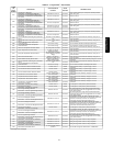
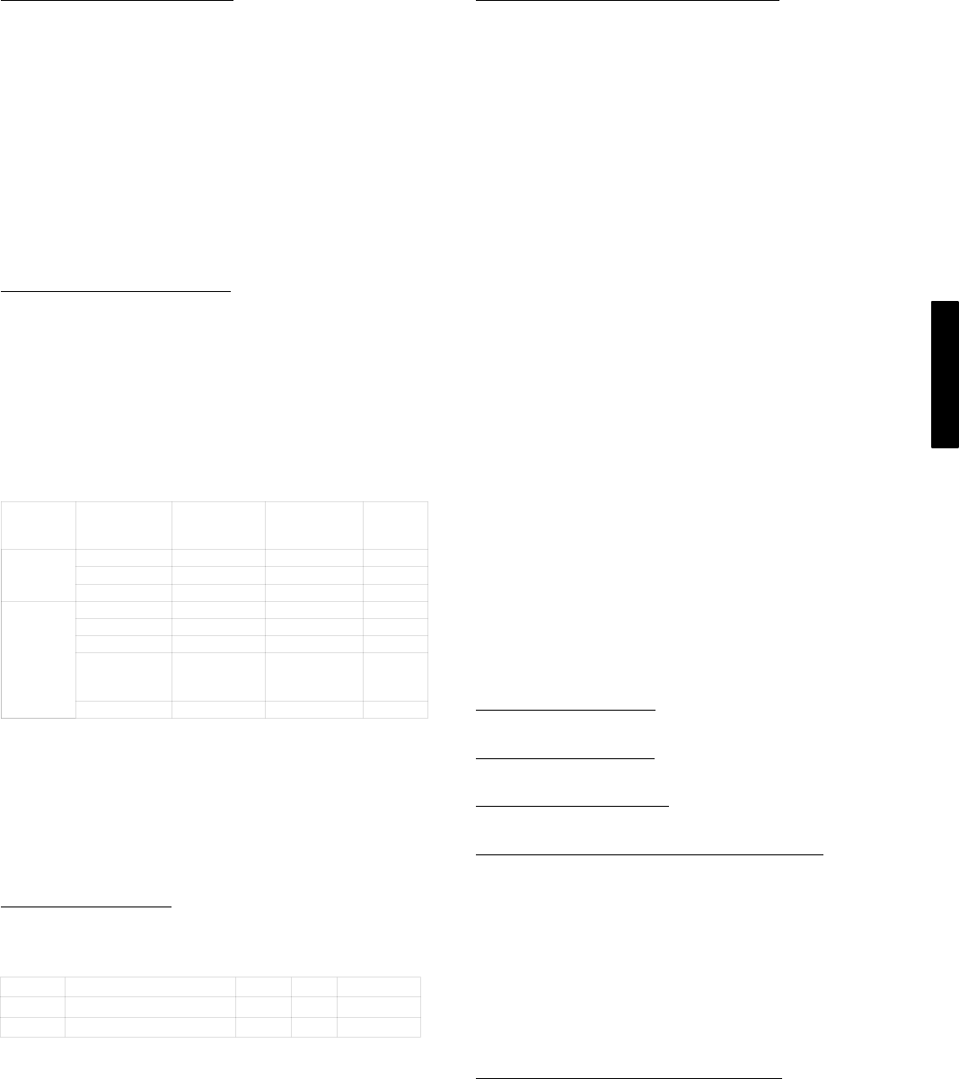
Table 11 – Cooling Fan Speed Determination
Number
of
Circuits
Cooling
Stages
Requested
Reheat
Stages
Requested
HVAC Mode
Fan
Speed
1
1 0 Cooling 100%
1 >0 Reheat1 100%
0 >0 Reheat2 FS.RH
>1
1 0 Cooling FS.CL
>1 0 Cooling 100%
>1 >0 Reheat1 100%
1 >0
Reheat1/
Reheat2
FS.CL
or
FS.RH
0 >0 Reheat2 FS.RH
Temperature Compensated Start
This logic is used when the unit is in the unoccupied state. The
control will calculate early Start Bias time based on Space
Temperature deviation from the occupied cooling and heating set
points. This will allow the control to start the unit so that the space
is at conditioned levels when the occupied period starts. This is
required for ASHRAE 90.1 compliance. A space sensor is required
for non-linkage applications.
Setting Up the System
The settings for temperature compensated start can be found in the
local display under Configuration→UNIT.
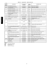
ITEM EXPANSION RANGE UNITS CCN POINT
TCS.C
Temp.Cmp.Strt.Cool Factr 0 ‐ 60 min TCSTCOOL
TCS.H
Temp.Cmp.Strt.Heat Factr 0 ‐ 60 min TCSTHEAT
Temp Comp Strt Cool Factr (TCS.C)
This is the factor for the start time bias equation for cooling.
Temp Comp Strt Heat Factr (TCS.H)
This is the factor for the start time bias equation for heating.
NOTE: Temperature compensated start is disabled when these
factors are set to 0.
Temperature Compensated Start Logic
The following conditions must be met for the algorithm to run:
Unit is in unoccupied state.
Next occupied time is valid.
Current time of day is valid.
Valid space temperature reading is available (sensor or CCN
network).
The algorithm will calculate a Start Bias time in minutes using the
following equations:
If (space temperature > occupied cooling set point)
Start Bias Time = (space temperature – occupied cooling set
point)* TCS.C
If (space temperature < occupied heating set point)
Start Bias Time = (occupied heating set point – space
temperature)*TCS.H
When the Start Bias Time is greater than zero the algorithm will
subtract it from the next occupied time to calculate the new start
time. When the new start time is reached, the Temperature
Compensated Start mode is set, the fan is started and the unit
controlled as in an occupied state. Once set, Temperature
Compensated mode will stay on until the unit goes into the
Occupied mode. The Start Bias Time will be written into the CCN
Linkage Equipment Table if the unit is controlled in DAV mode. If
the Unoccupied Economizer Free Cool mode is active when
temperature compensated start begins, the Unoccupied Free Cool
mode will be stopped.
NOTE: The maximum minutes Start Bias can be is 180.
Carrier Comfort Network (CCN)R Configuration
It is possible to configure the ComfortLink control to participate
as an element of the Carrier Comfort Network (CCN) system
directly from the local display. This section will deal with
explaining the various programmable options which are found
under the CCN sub-menu in the Configuration mode.
The major configurations for CCN programming are located in the
local displays at Configuration→CCN. See Appendix A.
CCN Address (CCN.A)
This configuration is the CCN address the rooftop is assigned.
CCN Address (CCN.B)
This configuration is the CCN bus the rooftop is assigned.
CCN Baud Rate (BAUD)
This configuration is the CCN baud rate.
CCN Time/Date Broadcast (BROD"B.TIM)
If this configuration is set to ON, the control will periodically send
the time and date out onto the CCN bus once a minute. If this
device is on a CCN network then it will be important to make sure
that only one device on the bus has this configuration set to ON. If
more than one time broadcaster is present, problems with the time
will occur.
NOTE: Only the time and date broadcaster can perform
daylight savings time adjustments. Even if the rooftop is stand
alone, the user may want to set this to ON to accomplish the
daylight/savings function.
CCN OAT Broadcast (BROD"B.OAT)
If this configuration is set to ON, the control will periodically
broadcast its outside-air temperature at a rate of once every 30
minutes.
48/50PG and PM