


51
Phase Loss Protection
The phase loss protection option will monitor the three-phase
electrical system to provide phase reversal and phase loss
protection.
Phase Reversal Protection
If the control senses an incorrect phase relationship, the relay (K1)
will be de-energized (opening its contact). If the phase relationship
is correct, the relay will be energized. The control has a self-bypass
function after a pre-set time. If the control determines that the three
phases stay in a correct relationship for 10 consecutive minutes, the
relay will stay energized regardless of the phase sequence of three
inputs as long as 24-vac control voltage is applied. This self-bypass
function will be reset if all three phases are restored in a phase loss
event.
Phase Loss Protection
If the reverse rotation board senses any one of the three phase
inputs has no AC voltage, the relay will be de−energized (opening
its contact). This protection is always active as long as 24-vac
control voltage is applied, and is not affected by the self by-pass
function of the phase sequence monitoring function. However, in
the event of phase loss, the relay will be re-energized only if all
three phases are restored and the three phases are in the correct
sequence.
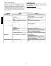
A red LED is provided to indicate the function of the board. See
the table below.
LED STATUS FUNCTION
On Continuously Relay contact closed (normal operation).
Blinking
Relay contact open (phase loss or phase
reversal has occurred) — No power will be
supplied to the control system.
Off 24 vac control power not present (off).
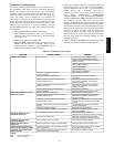
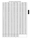
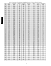
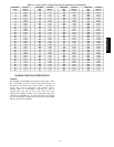
Thermistor Troubleshooting
The electronic control uses thermistors to sense temperatures used
to control operation of the unit. Resistances at various temperatures
are listed in Table 20 and 21. Thermistor pin connection points are
shown in the Major System Components section. The general
locations of the thermistors are shown the Major System
Components section.
Air Temperatures
Air temperatures are measured with 10 kilo-ohm thermistors. This
includes supply-air temperature (SAT), outdoor-air temperature
(OAT), space temperature sensors (T55, T56, T58), and return air
temperature (RAT).
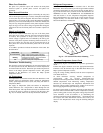
The supply air temperature (SAT) and outdoor air temperature
(OAT) thermistors use a snap-mount to attach through the unit
sheet metal panels. The snap-mount tabs must be flattened on the
tip end of the sensor to release for removal from the panel. (See
Fig. 22.) To reinstall, make sure the snap-mount tabs extend out.
Refrigerant Temperatures
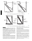
Condenser coil temperatures are measured with 5 kilo-ohm
thermistors. These measurements provide an approximate saturated
condensing temperature for each circuit (SCT.A, SCT.B, SCT.C).
Fig. 23−24 show the factory locations for the SCT thermistors on
48/50PG03−16 units. On 48/50PG20−28 and 48/50PM16−28
units the location is on the component arrangement diagrams.
Ensure that thermistors are placed at the correct location and are
snapped securely over the return bend so that contact is made
between the thermistor and the tube.
C07015
Fig. 22 − SAT and OAT Thermistor Mounting
Thermistor/Temperature Sensor Check
A high quality digital volt-ohmmeter is required to perform this
check.
Connect the digital voltmeter across the appropriate thermistor
terminals at the J8 terminal strip on the Main Base Board (see
Major System Components section).
Using the voltage reading obtained, read the sensor temperature
from Table 20 and 21.
To check thermistor accuracy, measure temperature at
probe location with an accurate thermocouple-type
temperature-measuring instrument. Insulate thermocouple to avoid
ambient temperatures from influencing reading. Temperature
measured by thermocouple and temperature determined from
thermistor voltage reading should be close, within 5°F if care was
taken in applying thermocouple and taking readings.
If a more accurate check is required, unit must be shut down and
thermistor removed and checked at a known temperature (freezing
point or boiling point of water) using either voltage drop measured
across thermistor at the J8 terminal, or by determining the
resistance with unit shut down and thermistor disconnected from
J8. Compare the values determined with the value read by the
control in the Temperatures mode using the Scrolling Marquee
display.
48/50PG and PM