


72
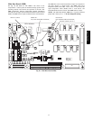
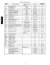
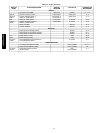
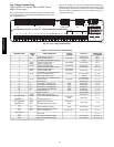
Table 23 – MBB Connections
DISPLAY
NAME
POINT DESCRIPTION SENSOR LOCATION TYPE OF I/O
CONNECTION
PIN NUMBER
INPUTS
Input power from TRAN1 control box 24 VAC J1, 1-3
HUM
IGC Fan Request or
Humidistat switch input
gas section /
space
switch input J6, 4
FDWN Fire shutdown switch supply/return/space switch input J6, 6
G Thermostat G (Fan) space switch input J7, 2
W2 Thermostat W2 (2nd Stage Heat) space switch input J7, 4
W1 Thermostat W1 (1st Stage Heat) space switch input J7, 6
Y2 Thermostat Y2 (2nd Stage Cool) space switch input J7, 8
Y1 Thermostat Y1 (1st Stage Cool) space switch input J7, 10
FIL.S Filter status switch indoor fan section switch input J9, 2-3
CS.A1 Compressor A1 Current Sensor control box 0-5vdc digital input J9, 4-6
CS.B1 or
CS.A2
Compressor B1 or
A2 Current Sensor
control box 0-5vdc digital input J9, 7-9
CS.C1 or
CS.B1
Compressor C1or
B1 Current Sensor
control box 0-5vdc digital input J9, 10-12
SPT Space temperature (T55/56) space 10k thermistor J8, 1-2
SPTO or
RAT
Space temperature offset (T56) or
Return air temperature
space or return 10k thermistor J8, 2-3
OAT Outdoor air temperature outdoor coil support 10k thermistor J8, 5-6
SAT Supply air temperature
indoor fan housing, or
supply duct
10k thermistor J8, 7-8
SCT.A Saturated condenser temperature, circuit A outdoor coil, circuit A 5k thermistor J8, 9-10
SCT.B Saturated condenser temperature, circuit B outdoor coil, circuit B 5k thermistor J8, 11-12
SCT.C Saturated condenser temperature, circuit C outdoor coil, circuit C 5k thermistor J8, 13-14
FAN.S Fan status switch indoor fan section switch input J8, 15-16
SSP.A Suction pressure, circuit A compressor A suction
0-5 VDC pressure
transducer
J8, 18-20
SSP.B Suction pressure, circuit B compressor B suction
0-5 VDC pressure
transducer
J8, 21-23
SSP.C Suction pressure, circuit C compressor C suction
0-5 VDC pressure
transducer
J8, 24-26
OUTPUTS
CRC Cooling Reheat Control relay J10, 3
CMP.C or
OFC.2
Compressor C1 relay or
Outdoor fan 2 relay
relay J10, 6
COMP.B Compressor B1 relay relay J10, 9
COMP.A Compressor A1 relay relay J10, 11
CCH or
OFC.3
OFC.1
Crankcase heat relay or
Outdoor fan 3 relay or
Outdoor fan 1 relay
relay J10, 13
OFC.2 or
RH2.B
Outdoor fan 2 relay or
Reheat 2 valve circuit B & C
relay J10, 16
OFC.1 or
RH2.A
Outdoor fan 1 relay or
Reheat 2 valve circuit A
relay J10, 19
IDF Indoor fan relay relay J10, 21
ALRM Alarm relay relay J10, 23
HT.1 Heat Stage 2 relay relay J10, 25
HT.2 Heat Stage 1 relay relay J10, 27
COMMUNICATION
Local Equipment Network (LEN)
communication J5, 1-3
Carrier Comfort Network (CCN) communication J5, 5-7
Network device power 24 VAC J5, 9-10
Scrolling Marquee Display (LEN) communication J4, 1-3
Scrolling Marquee Display power 24 VAC J4, 5-6
Optional ECB (LEN) communication J3, 1-3
Optional ECB power 24 VAC J2, 1-2
48/50PG and PM