


24
Free Cool PreOcc Time (FC.TM)
FC.TM is the configuration that determines how many minutes
before occupancy that free cooling can occur when set for
Preoccupancy (UEFC = 2).
Free Cool Low Temp Limit (FC.LO)
Unoccupied free cooling cannot occur if the Outdoor Air
Temperature (Temperature→ AIR.T→ OAT) is less than FC.LO.
Power Exhaust
To enable power exhaust, Configuration→ECON→PE.EN must
be set to ENBL. If power exhaust is enabled, Power Exhaust 1 will
turn on when the economizer position is greater than the value of
Configuration→ECON→PE.1. If power exhaust is enabled,
Power Exhaust 2 will turn on when the economizer position is
greater than the value of Configuration→ECON→PE.2. There are
small time delays to ensure that rapid cycling does not occur.
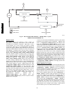
Optional Humidi−MiZert Dehumidification
System
Units with the factory−equipped Humidi−MiZer option are capable
of providing multiple modes of improved dehumidification as a
variation of the normal cooling cycle. The Humidi−MiZer option
includes additional valves in the liquid line and discharge line of
each refrigerant circuit, a small reheat condenser coil downstream
of the evaporator, and Motormaster variable−speed control of
some or all outdoor fans. The Humidi−MiZer Equipped
(Configuration→HMZR→REHT) configuration is factory set to
Yes for Humidi−MiZer equipped units. This enables
Humidi−MiZer operating modes and service test.
NOTE: If the unit is a Humidi−MiZer unit, this configuration
must always be set to yes. The Humidi−MiZer option does affect
the base unit wiring.
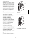
Humidi−MiZer operation requires installation and configuration of
either a space relative humidity sensor or a relative humidity switch
input. Space Humidity Switch (Configuration→UNIT→RH.SW)
set to 1 for use of a normally open switch or 2 for normally closed
switch. The switch is wired to field connection terminal board
terminals labeled HUMDISTAT. Set RH Sensor on OAQ Input
(Configuration→UNIT→RH.S) to Yes for use of a 4 to 20 mA
output RH sensor wired to field connection terminal board (TB)
terminals 1 and 4 (for loop powered). RH Sensor Value at 4ma
(Configuration→AIR.Q→H.4M) sets the % display for a 4mA
input from the relative humidity sensor. RH Sensor Value at 20ma
(Configuration→AIR.Q→H.20M) sets the % display for a 20mA
input from the relative humidity sensor.
Dehumidification Demand
When using a humidistat or switch input, the demand for
dehumidification is seen as Space Humidity Switch (Inputs
→GEN.I→HUM) being Low or High. A low value means
humidity level is good and a high value means that
dehumidification is needed. When using an RH sensor, the demand
is based on the Space Humidity Sensor (Inputs→AIR.Q→SP.RH)
value compared to the Space RH Occupied Setpoint
(Setpoints→RH.SP) during the occupied period and Space RH
Unoccupied Setpoint (Setpoints → RH.UN) during unoccupied
periods. If the Space Humidity Sensor (SP.RH) value is above the
Space RH Setpoint (RH.SP), then dehumidification is needed. If
the Space Humidity Sensor (SP.RH) value is below the Space RH
Setpoint (RH.SP) minus the Space RH Deadband
(Setpoints→RH.DB), then dehumidification is no longer needed.
If the unit is configured for space sensor control
(Configuration→UNIT →U.CTL = 3), then the setpoint Reheat
Heat SP Deadband (Setpoints→RH.HB) applies. This
configuration sets the offset above the heating set point at which a
unit in Reheat2 mode will turn off. This is a protection against over
cooling the space and causing a heat demand.
NOTE: When there is a dehumidification demand, the economizer
damper position is limited to it’s minimum damper position
(Operating Mode→ECON→EC.MP).
Reheat Modes
Dehumidification (reheat) is a cooling mode function. Refer to
Cooling Operation for cooling mode control. With Humidi−MiZer
units there are three additional HVAC Mode (HVAC) expanded
texts available for the user: Reheat1, Reheat2, and
Reheat1/Reheat2. Selection of the reheat mode for each refrigerant
circuit is determined by the dehumidification demand and the
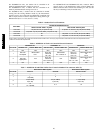
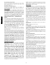
cooling demand. Table 10 shows the corresponding circuit mode
and output status for the different demand combinations. Units
with multiple circuits can operate with a combination of Reheat1
and Reheat2 circuits, as determined by the amount of space cooling
demand. See Appendix B for complete tables of unit operation
response to thermostat and humidity inputs.
NOTE: Compressor staging control for Humidi−MiZer units
requires that circuit A always operates when either circuits B or C
are on. This applies to normal operation, service test, and for
control alarm responses. This operation difference is required due
to the fact that the Motormaster outdoor fan control senses circuit
A only.
Operation of the revised refrigerant circuit for each mode is
described below.
NOTE: x = refrigerant circuit A, B, or C
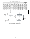
Normal Cooling
For 48/50PG03−16 units, refrigerant flows from the outdoor
condenser through the normally open Cooling Valve (CV.x) to the
expansion device. Reheat1 Valve (RH1.x) and Reheat2 Valve
(RH2.x) are closed. (See Fig. 9.)
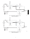
For 48/50PG20−28 and 48/50PM16−28 units, refrigerant flows
from the outdoor condenser through the de−energized 3−way valve
(RH.x) to the expansion device. Reheat2 Valve (RH2.x) is closed.
(See Fig. 12.)
Reheat 1 (Subcooling Mode)
This mode increases latent cooling and decreases sensible cooling
compared to normal cooling.
For 48/50PG03−16 units, refrigerant flows from the outdoor
condenser, through the normally open Reheat 1 Valve (RH1.x),
and through the reheat condenser coil to the expansion device.
Cooling Valve (CV.x) and Reheat2 Valve (RH2.x) are closed. (See
Fig. 10.)
For 48/50PG20−28 and 48/50PM16−28 units, refrigerant flows
from the outdoor condenser, through the energized 3−way Valve
(RH1.x), and through the reheat condenser coil to the expansion
device. Cooling Reheat2 Valve (RH2.x) is closed. (See Fig. 13.)
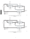
Reheat 2 (Hot Gas Reheat Mode)
This mode provides maximum latent cooling with little to no
sensible capacity. This mode can operate to provide
dehumidification when there is no cooling demand. Similar to
Reheat 1 mode, refrigerant flows from the outdoor condenser,
through the normally open Reheat 1 Valve (RH1.x), or through the
energized 3−way valve (RH.1x), and through the reheat condenser
coil to the expansion device. Reheat2 Valve (RH2.x) is open which
provides some compressor discharge gas to the reheat condenser to
further increase the reheat of the evaporator air stream (See Fig. 11
or 14 based on unit and size).
NOTE: Humidi−MiZer outdoor fan configurations are dependent
on the specific unit and should not be changed. The configurations
are provided in case a field replacement of a control board occurs
and the settings need to be checked or manually configured. See
Appendix A for range and defaults.
48/50PG and PM