


37
This synchronization of data optimizes the efficiency of the unit
and the zones to operate at peak system performance at all times.
This information can be seen in linkage maintenance tables of the
Linkage Coordinator and the RTU; it is updated at approximately
1−minute intervals.
Cooling and heating operation is slightly modified during Linkage
control. A PID loop is run to calculate required stages. This is
necessary because in stand alone operation, the unit tries to
anticipate the space. With Linkage, the unit must try to satisfy the
demand as soon as possible. The PID configurations are in
Configuration→PID. These values have been field tested and the
default values should NOT BE CHANGED.
For information on set up and configuration, see the Space
Temperature Control−CCN Linkage text in the Controls Quick
Start section of this book.
For additional information on the Linkage Coordinator or Zone
Controllers, please refer to their appropriate manuals.
Alarm Handling
There are a variety of different alerts and alarms in the system.
Alerts are indicated by TXXX (where XXX is the alert number) on
the display and generally signify that the improperly functioning
circuit can restart without human interaction. If an alarm occurs,
indicated by AXXX (where XXX is the alarm number), the
damaged circuit will generally not restart without an alarm reset via
the Scrolling Marquee display or CCN.
The response of the control system to various alerts and alarms
depends on the seriousness of the particular alert or alarm. In the
mildest case, an alert does not affect the operation of the unit in any
manner. An alert can also cause a “strike.” A “striking” alert will
cause the circuit to shut down for 15 minutes. This feature reduces
the likelihood of false alarms causing a properly working system to
be shut down incorrectly. If three strikes occur before the circuit
has an opportunity to show that it can function properly, the circuit
will strike out, causing the shutdown alarm for that particular
circuit. Once activated, the shutdown alarm can only be cleared via
an alarm reset.
However, circuits with strikes will be given an opportunity to reset
their strike counter to zero. As discussed above, a strike typically
causes the circuit to shut down. Fifteen minutes later, that circuit
will once again be allowed to run. If the circuit is able to run for 1
minute, its replacement circuit will be allowed to shut down (if not
required to run to satisfy requested stages). However, the
“troubled” circuit must run continuously for a user defined time
(Configuration→COOL→RST.C) with no detectable problems
before the strike counter will be reset to zero. Default value is
5 minutes.
CCN Alarm Broadcast
Operators of CCN networks might not want to be notified of
“striking” alerts for refrigerant circuits until the circuit has been
shut down due to 3 strikes. Set the cooling configuration of Alert
Each Strike (Configuration→COOL→ALM.N on display,
ALM_NOW on CCN) to YES to broadcast each circuit strike alert.
Set Alert Each Strike to NO to broadcast only circuit shut down.
Alert Each Strike configuration is ignored during Service Test and
all alerts are broadcast.
Alarm Relay Output
The alarm relay output is a normally open 24 vac output between
field connection terminal board terminals C and X. Selection of
which alerts and alarms will result in closing of the alarm relay
may be set in the Alarm Relay Configuration
(Configuration→ALM.O). Setting a configuration to YES will
result in the alarm output relay, ALRM, status of ON and 24 vac
between C and X when that particular condition is in an alarm
state. Setting a configuration to NO will result in no action by the
alarm output relay for that particular condition.
NOTE: An accessory filter switch can be used along with the
alarm relay output function to indicate dirty filter service need.
See the Troubleshooting section for more information on viewing,
diagnosing, and clearing alerts and alarms.
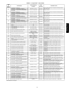
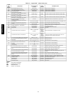
TROUBLESHOOTING
The Scrolling Marquee display shows the actual operating
conditions of the unit while it is running. If there are alarms or
there have been alarms, they will be displayed in either the current
alarm list or the history alarm list. (See Table 14.) The Service Test
mode allows proper operation of the compressors, fans, and other
components to be checked while the unit is not operating. See
Service Test.
Complete Unit Stoppage
There are several conditions that can cause the unit not to provide
heating or cooling:
If an alarm is active which causes the unit to shut down,
diagnose the problem using the information provided in Alarms
and Alerts section below.
Cooling and heating loads are satisfied.
Programmed occupancy schedule.
General power failure.
Tripped CB1, CB2, or CB3 (24-volt transformer circuit
breakers).
Blown fuse (FU1−4)
Unit is turned off through the CCN network.
If supply-air temperature is less than the Minimum SAT Lower
Level (SAT.L) configuration value, unit cannot cool.
If outdoor-air temperature is less than the Compressor Lockout
Temperature (CA.LO, CB.LO, CC.LO) configuration value, unit
cannot cool.
If outdoor-air temperature is greater than the Heating Lockout
Temperature (HT.LO) configuration value, unit cannot heat.
Restart Procedure
Before attempting to restart the machine, check the alarm list to
determine the cause of the shut down. If the shutdown alarm for a
particular control function has occurred, determine and correct the
cause before allowing the unit to run under its own control again.
When there is problem, the unit should be diagnosed in Service
Test mode. The alarms must be reset before the control function
can operate in either Normal mode or Service Test mode.
Alarms and Alerts
Viewing and Clearing Unit Alarms
Presence of active alarms will be indicated on the Scrolling
Marquee display by the Alarm Status light turning on and by the
number of active alarms being displayed in the automatic View of
Run Status. Presence of active alarms may also be signaled on the
Alarm Output terminals. Each alarm may also be broadcast on the
CCN network. Active alarms and past alarm history can be
reviewed and cleared via the local display or a CCN device. The
following menu locations are used for the local display:
Alarms"R.CURR (Reset All Current Alarms)
Change to YES to reset all active alarms. Turning unit power off
will also reset all current alarms.
48/50PG and PM