


55
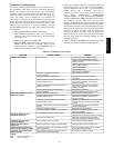
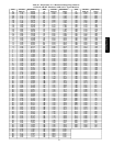
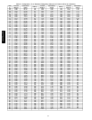
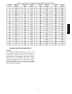
Table 22 – Pressure (psig) vs. Voltage Drop Values for Suction Pressure Transducers
PRESSURE
(psig)
VOLTAGE
DROP (V)
PRESSURE
(psig)
VOLTAGE
DROP (V)
PRESSURE
(psig)
VOLTAGE
DROP (V)
PRESSURE
(psig)
VOLTAGE
DROP (V)
0
0.465
68
1.135
136
1.804
204
2.474
2
0.485
70
1.154
138
1.824
206
2.493
4
0.505
72
1.174
140
1.844
208
2.513
6
0.524
74
1.194
142
1.863
210
2.533
8
0.544
76
1.214
144
1.883
212
2.553
10
0.564
78
1.233
146
1.903
214
2.572
12
0.583
80
1.253
148
1.922
216
2.592
14
0.603
82
1.273
150
1.942
218
2.612
16
0.623
84
1.292
152
1.962
220
2.631
18
0.642
86
1.312
154
1.982
222
2.651
20
0.662
88
1.332
156
2.001
224
2.671
22
0.682
90
1.351
158
2.021
226
2.690
24
0.702
92
1.371
160
2.041
228
2.710
26
0.721
94
1.391
162
2.060
230
2.730
28
0.741
96
1.410
164
2.080
232
2.749
30
0.761
98
1.430
166
2.100
234
2.769
32
0.780
100
1.450
168
2.119
236
2.789
34
0.800
102
1.470
170
2.139
238
2.809
36
0.820
104
1.489
172
2.159
240
2.828
38
0.839
106
1.509
174
2.178
242
2.848
40
0.859
108
1.529
176
2.198
244
2.868
42
0.879
110
1.548
178
2.218
246
2.887
44
0.898
112
1.568
180
2.237
248
2.907
46
0.918
114
1.588
182
2.257
250
2.927
48
0.938
116
1.607
184
2.277
252
2.946
50
0.958
118
1.627
186
2.297
254
2.966
52
0.977
120
1.647
188
2.316
256
2.986
54
0.997
122
1.666
190
2.336
258
3.005
56
1.017
124
1.686
192
2.356
260
3.025
58
1.036
126
1.706
194
2.375
262
3.045
60
1.056
128
1.726
196
2.395
264
3.065
62
1.076
130
1.745
198
2.415
266
3.084
64
1.095
132
1.765
200
2.434
268
3.104
66
1.115
134
1.785
202
2.454
270
3.124
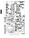
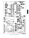
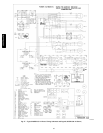
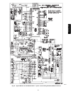
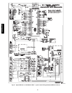
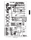
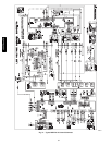
MAJOR SYSTEM COMPONENTS
General
The 48/50PG and 48/50PM single package rooftop units contain
the ComfortLink electronic control system that monitors all
operations of the rooftop. The control system is composed of
several main control components and available factory-
installed options or field-installed accessories as listed in
sections below. See Fig. 25−36 for the control and power
schematics for 48/50PG. See Fig. 31−36 for the control and power
schematics for 48/50PM. Fig. 37 shows the layout of the control
box, unit, and thermistor and transducer locations for the 48/50PG
and Fig. 38−39 for the 48/50PM.
48/50PG and PM