


22
Space Sensor Control
Space sensor staging control is an adaptive anticipation control that
weighs the actual space demand against the trend of that demand.
It also honors stage time guards and supply air limits. The demand
for heating in the space is displayed as the Heating Demand (Run
Status→HEAT→DMD.H). The control tries to anticipate the
change in the space because of its current stage status. This
anticipation is based on the Heat Demand Trend (Operating Modes
→HEAT→TRD.H). This trend will show the control how the
space is reacting to the current running conditions and help it
decide when to add or remove one stage from the requested stages.
The Heat Stage Increase Time (Configuration→HEAT→H.INC)
or the Heat Stage Decrease Time (Configuration→HEAT
→H.DEC) has to expire before another stage can be added or a
stage can be subtracted. If at any time the Supply−Air Temperature
(SAT) rises above the Maximum Supply Air Temperature Lower
Level (Configuration→HEAT→SAT→SAM.L), the requested
stages will not be allowed to increase. If at any time the SAT rises
above the Maximum Supply Air Temperature Upper Level
(Configuration→HEAT→SAT→SAM.U), the requested stages
will be reduced by one without honoring H.DEC.
Heat Relay Control
The heat relay control is responsible for energizing or
de−energizing the MBB’s heat stage relays and works hand in hand
with the staging control. As the staging control requests stages, the
heat relay control determines what actual heat relays are available
or energized and tries to provide stages for what is requested. The
availability of a heat relays depends on heat being installed, how
many stages, and time guards. The type of Heat Installed
(Configuration→HEAT→HT.TY) must be set for gas or electric
for any stages to be available. The Number of Heat Stages
(Configuration→HEAT→N.HTR) configuration tells the control
how many heat relays can be used. Heat Stage 1Timeguard (Run
Status→HEAT→TG.H1) and Heat Stage 2 Timeguard (Run
Status→HEAT→TG.H2) display the time a respective heat relay
has before it is available for use. The available stages at any given
time are displayed as Available Heating Stages (Run Status
→HEAT→AVL.H). The actual heat relays on at any given time
are displayed as Actual Heating Stages (Operating Modes→HEAT
→ACT.H). Heat Stage 1 Relay (Run Status→HEAT→HT.1) and
Heat Stage 2 Relay (Run Status→HEAT→HT.2) are displayed on
when the respective relay is energized. There are time guards to
protect from short cycling, Heat Minimum On Time
(Configuration→HEAT→MRT.H) and Heat Minimum Off Time
(Configuration→HEAT→MOT.H) apply before a heat relay can
be turned back on or turned off.
Integrated Gas Controller (IGC)
The heat staging is determined as described above and the
Integrated Gas Controller (IGC) initiates the gas heat module
start−up. The Integrated Gas Controller (IGC) minimum on−time
of 1 minute will be followed even if Heat Minimum On Time
(Configuration→HEAT→MRT.H) is lower and during Service
Test. If the IGC temperature limit switch opens within 10 minutes
of the end of the gas heat cycle, the next fan off delay will be
extended by 15 seconds. The maximum delay is 3 minutes. Once
modified by the IGC, the fan off delay will not change back to the
configured Fan−off Delay, Gas Heat (Configuration→HEAT
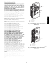
→FOD.G) unless power is reset to the control. A light emitting
diode (LED) is provided on the IGC to indicate status. During
normal operation the LED is continuously on. See the
Troubleshooting section if the LED is off or flashing. The IGC is
located behind the gas section access panel door.
When the control energizes Heat Stage 1 Relay (Run Status
→HEAT→HT.1), power is sent to the W terminal on the IGC
board. A check is made to ensure that the rollout switch and limit
switch are closed. The induced−draft motor is then energized, and
when speed is proven with the Hall Effect sensor on the motor, the
ignition activation period begins. The burners will ignite within 5
seconds. If the burners do not light, there is a 22−second delay
before another 5−second attempt. If the burners still do not light,
this sequence is repeated for 15 minutes. After the 15 minutes have
elapsed, if the burners still have not lit, heating is locked out. The
control will reset when the request for heat is temporarily removed.
When ignition occurs, the IGC board will continue to monitor the
condition of the rollout switch, limit switches, the Hall Effect
sensor, as well as the flame sensor. If the unit is controlled through
a room thermostat or space sensor set for fan auto, 45 seconds after
ignition occurs the indoor−fan motor will be energized (and the
outdoor−air dampers will open to their minimum position). If for
some reason the over temperature limit opens prior to the start of
the indoor fan blower, on the next attempt, the 45−second delay
will be shortened to 5 seconds less than the time from initiation of
heat to when the limit tripped. Gas will not be interrupted to the
burners and heating will continue. Once modified, the fan on delay
will not change back to 45 seconds unless power is reset to the
control. When the control energizes Heat Stage 2 Relay (Run
Status→HEAT→HT.2), power is supplied to the second stage of
the main gas valve. If both stage 1 and stage 2 of the gas valve
close, gas will be turned off to the main burners.
48/50PG and PM