


9
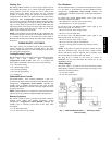
Space Temperature Sensor Control − Direct Wired
(T−55 or T−56 or T−59)
Wire accessory space temperature sensor(s) to the T-55 terminals
on the field connection terminal board located at the unit control
box. Refer to Field-Installed Accessories section for additional
information.
The Unit Control Type configuration, Configuration
→UNIT→U.CTL, must be set to Space Sensor (3). The jumper
wire in the installer’s packet must be connected between R and W1
for heating mode to operate.
T−58 Communicating Room Sensor
Install the T-58 communicating thermostat. Connect the CCN
communication bus from the T-58 to the CCN terminals on the
field connection terminal board located at the unit control box.
Configure the unit’s CCN communication element number, bus
number, and baud rate. Configure the T−58’s CCN communication
bus number and baud rate the same as the unit, while the element
number has to be different. Configure the T−58 to send SPT to the
unit’s element number. Refer to the Field−Installed Accessories
section for additional information.
The Unit Control Type configuration, Configuration
→UNIT→U.CTL, must be set to Space Sensor (3). The jumper
wire in the installer’s packet must be connected between R and W1
for heating mode to operate.
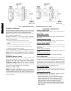
CCN Linkage Control
The CCN communication must be properly configured for the
48/50PG and 48/50PM units and all other devices. Linkage
configuration is automatically done by the supervisory CCN
Linkage device.
The Unit Control Type configuration, Configuration
→UNIT→U.CTL must be set to Space Sensor (3). The jumper
wire in the installer’s packet must be connected between R and W1
for heating mode to operate.
Installation of an accessory supply air temperature (SAT) sensor in
the supply duct is recommended for Linkage applications. A
supply duct SAT measurement is valid for heating mode display,
while the factory-standard internal SAT is not valid for heating due
to its location upstream of the heating section. When installing the
supply duct SAT, the heating mode display is enabled by setting
Configuration→HEAT→SAT.H to ENBL.
Installation of an accessory return air temperature (RAT) sensor in
the return duct and wired to the space sensor input is recommended
for Linkage applications. This will allow the unit to continue to
run if Linkage communication is lost.
System Pilot − Communication Space Sensor
Install the System Pilot and connect the CCN communication bus
from it to the unit’s CCN connection on the low voltage terminal
board. Configure the unit’s CCN communication element number,
bus number, and baud rate. Refer to the System Pilot’s installation
instructions for configuring it to be used as a space temperature and
attaching it to a unit.
Thermidistat Control
The thermidistat is a thermostat and humidistat combined
and the inputs are provided on the field connection
terminal board. The unit control type configuration,
Configuration→UNIT→U.CTL, default value is for thermostat
(2) so there is no need to configure this item. The thermostat
control type configuration, Configuration→UNIT→T.CTL,
selects the unit response to the thermostat inputs above. The space
humidity switch configuration, Configuration→UNIT→RH.SW,
identifies the normally open or normally closed status of this input
at LOW humidity, and the input is the Humidistat 1 terminal (only
on Humidi-MiZer units).
Space Humidistat Control
For units with the factory Humidi-MiZer option, the
humidistat input is provided on the field connection
terminal board. The Space Humidity Switch configuration,
Configuration→UNIT→RH.SW, identifies the normally open or
normally closed status of this input at LOW humidity. Humidistat
2 terminal is the 24 VAC source for dry contact and the Humidistat
1 terminal is the signal input.
NOTE: On units with Humidi-MiZer, the Humidistat terminals
1 and 2 are the same as the Fire Shutdown terminals 1 and 2 on a
standard unit. See Fire Shutdown section.
Relative Humidity Sensor Control
For units with the factory installed Humidi-MiZer option and the
economizer option (with the ECB−economizer control board), the
humidity sensor input is provided on the field connection terminal
board (TB1/TB2). The sensor can be used in addition to or instead
of a humidistat or thermidistat. The RH Sensor on OAQ Input
configuration, Configuration→UNIT→RH.S=YES, identifies that
the sensor is being used instead of an OAQ sensor. Adjust RH
setpoints as needed. Terminal 1 is the 24vdc loop power and
Terminal 4 is the 4−20 mA signal input. Refer to the Field Installed
Accessories and Humidi-MiZer Operation sections for more
information.
CCN Communication
Configure Configuration→CCN→CCN.A to desired element
number. (Default is 1.) Configure Configuration"CCN" CCN.B
to desired bus number. (Default is 0.) Configure
Configuration→CCN→BAUD to desired code number for baud
rate (Default is 3 = 9600 baud).
Accessories
Below are quick configuration settings for field installed
accessories. If these accessories were installed by the factory, they
will already be configured. See the Field−Installed Accessories
section, third party control, control connection tables, and CCN or
Display parameter tables for any accessories not mentioned below
and any additional information on accessories.
Economizer
If an Economizer accessory was field installed, the unit must be
configured for it by setting Configuration"ECON"EC.EN to
YES. The default settings for the other economizer configurations
should be satisfactory. If they need to be changed, additional
information about these configuration settings can be found in the
Economizer section.
Power Exhaust
If a Power Exhaust accessory was field installed, the unit must be
configured for it by setting Configuration"ECON"PE.EN to
ENBL. The default settings for the other power exhaust
configurations should be satisfactory. If they need to be changed,
additional information about these configurations can be found in
the Power Exhaust section.
Electric Heat
If an Electric Heat accessory was field installed, the unit must be
configured for it by setting Configuration→HEAT→HT.TY to a
value of 2. The number of electric heat stages must be configured
by setting Configuration→HEAT→N.HTR per the installed
heater.
Fire Shutdown
If a Fire Shutdown or Smoke Detector accessory was field
installed, the unit must be configured for it by setting
Configuration→UNIT→FS.SW to normally open (1) or normally
closed (2) when there is not a fire alarm. Normally open (1) is the
preferred configuration.
48/50PG and PM