


5
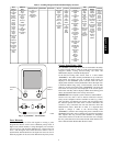
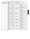
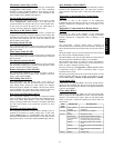
Table 2 – Scrolling Marquee Mode and Menu Display Structure
RUN
STATUS
SERVICE
TEST
TEMPERATURES PRESSURES SETPOINTS INPUTS OUTPUTS CONFIGURATION
TIME
CLOCK
OPERATING
MODES
ALARMS
Auto View
of
Run Status
(VIEW)
↓
Software
Version
Numbers
(VERS)
↓
Control
Modes
(MODE)
↓
Cooling
Status
(COOL)
↓
Heating
Status
(HEAT)
↓
Economizer
Status
(ECON)
↓
Outside Air
Unit Status
(OAU)
↓
Component
Run Hours
(HRS)
↓
Component
Starts
(STRT)
Service Test
Mode
(TEST)
↓
Test Indepen
dent
Outputs
(INDP)
↓
Test Fans
(FANS)
↓
Test Cooling
(COOL)
↓
Test
Humidi‐MiZer™
(HMZR)
↓
Test Heating
(HEAT)
Air
Temperatures
(AIR.T)
↓
Refrigerant
Temperatures
(REF.T)
Thermostat
Inputs
(STAT)
↓
General In
puts
(GEN.I)
↓
Current
Sensor In
puts
(CS.IN)
↓
Air Quality
Inputs
(AIR.Q)
Fan
Outputs
(FANS)
↓
Cool
Outputs
(COOL)
↓
Heat
Outputs
(HEAT)
↓
Economiz
er
Outputs
(ECON)
↓
Alarm
Relay
(ALRM)
Display
Configuration
(DISP)
↓
Unit
Configuration
(UNIT)
↓
Cooling
Configuration
(COOL)
↓
Humidi‐MiZer™
Config.
(HMZR)
↓
Heating
Configuration
(HEAT)
↓
Economizer
Configuration
(ECON)
↓
Air Quality
Cfg.
(AIR.Q)
↓
Outside Air Unit
Configuration
(OAU)
↓
Adaptive Fan
Configuration
(A.FN)
↓
Alarm Relay
Config.
(ALM.O)
↓
Sensor
Calibration
(TRIM)
↓
CCN
Configuration
(CCN)
Time of
Day
(TIME)
↓
Month,
Date
Day and
Year
(DATE)
↓
Daylight
Savings
Time
(DST)
↓
Local Time
Schedule
(SCH.L)
↓
Local
Holiday
Schedules
(HOL.L)
Control
Modes
(MODE)
↓
Cool Mode
Diagnostic
(COOL)
↓
Heat Mode
Diagnostic
(HEAT)
↓
Economizer
Diagnostic
(ECON)
↓
Outside
Air Unit
Diagnostic
(OAU)
↓
Demand
Listing
(DMD.L)
Reset All
Current
Alarms
(R.CURR)
↓
Reset
Alarm
History
(R.HIST)
↓
Currently
Active
Alarms
(CURR)
↓
Alarm
HIstory
(HIST)
SCROLL
+
-
NAVIGATE/
EXIT
MODIFY
/
SELECT
PAGE
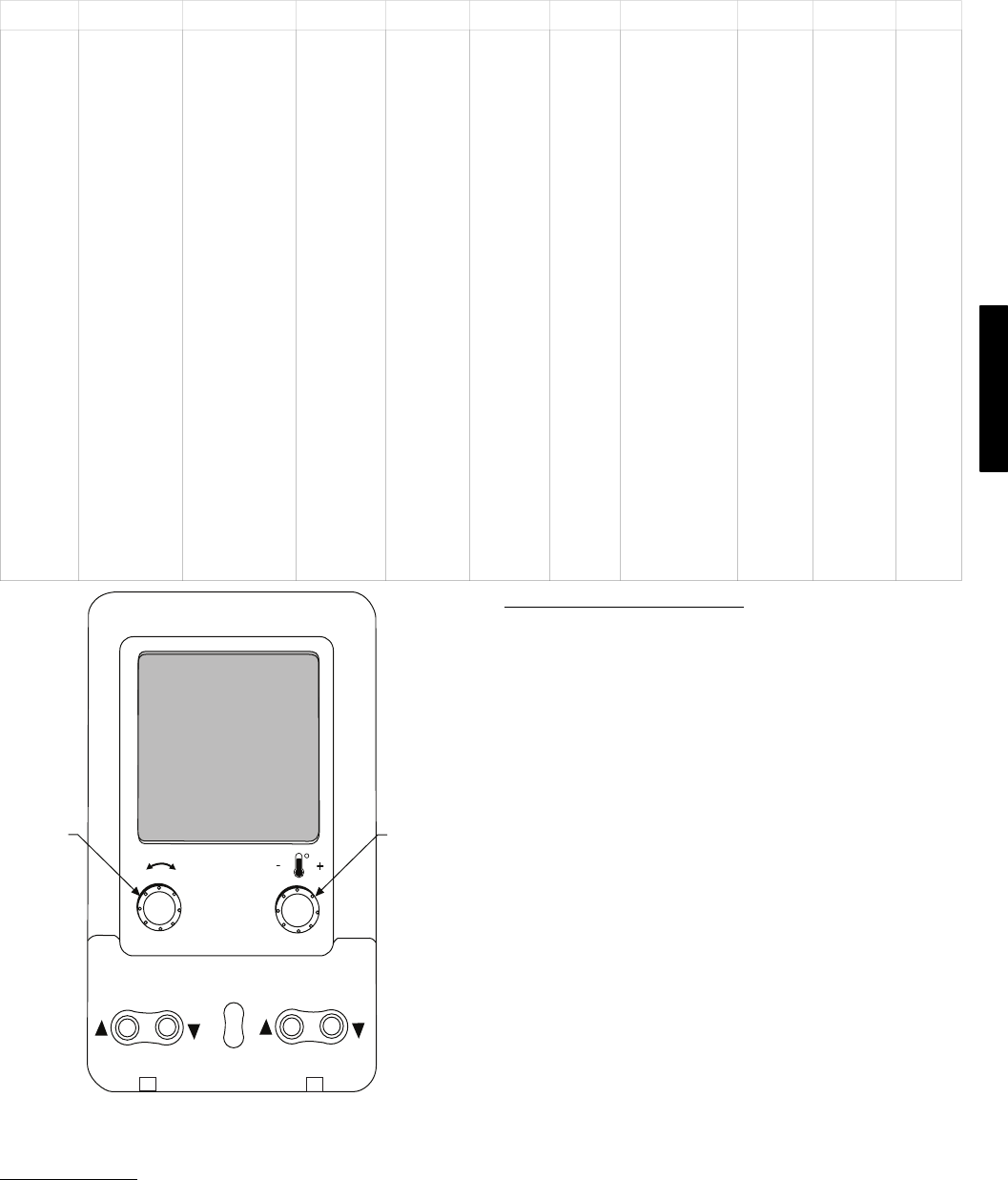
C06322
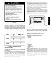
Fig. 3 − System Pilott User Interface
Force Hierarchy
There is a hierarchy in CCN with regards to forcing a point.
Programs and devices write a force at different priority levels. A
higher level (smaller number, 1 being the highest) will override a
lower level force. The Scrolling Marquee uses a Control Force at
level 7. The Navigator writes a Service Force which is level 3.
System Pilots and Touch Pilots write Supervisor Forces at level 4.
Network programs can be set to write different level priority forces.
Generic Status Display Table
The GENERIC points table allows the service/installer the ability
to create a custom table in which up to 20 points from the 5 CCN
categories (Points, Config, Service−Config, Set Point, and
Maintenance) may be collected and displayed.
In the Service−Config table section, there is a table named
“GENERICS.” This table contains placeholders for up to 20 CCN
point names and allows the user to decide which points are
displayed in the GENERIC points sub−table under the status
display table. Each one of these placeholders allows the input of an
8−character ASCII string. Using a CCN interface, enter the Edit
mode for the Service−Config table “GENERICS” and enter the
CCN name for each point to be displayed in the custom points
table in the order they will be displayed. When done entering point
names, download the table to the rooftop unit control.
IMPORTANT: The computer system software (ComfortVIEW,
Service Tool, etc.) that is used to interact with CCN controls,
always saves a template of items it considers as static (e.g., limits,
units, forcibility, 24−character text strings, and point names) after
the software uploads the tables from a control. Thereafter, the
software is only concerned with run time data like value and
hardware/force status. With this in mind, it is important that
anytime a change is made to the Service−Config table
“GENERICS” (which in turn changes the points contained in the
GENERIC point table), that a complete new upload be performed.
This requires that any previous table database be completely
removed first. Failure to do this will not allow the user to display
the new points that have been created and the CCN interface will
have a different table database than the unit control.
48/50PG and PM