


12
SERVICE TEST
The Service Test function can be used to verify proper operation of
compressors, heating stages, Humidi−MiZer System, indoor fan,
outdoor fans, power exhaust fans, economizer, crankcase heaters,
and the alarm relay. Use of Service Test is recommended at initial
system start up and during troubleshooting (See Table 4 for point
details).
Service Test mode has the following changes from normal
operation:
Outdoor air temperature limits for cooling circuits, economizer,
and heating are ignored. Normal compressor time guards and
other staging delays are reduced to 30 seconds or less.
Circuit alerts are limited to 1 strike (versus 3) before changing to
alarm shut down state.
The status of ALM.N is ignored so all alerts and alarms are
broadcast on CCN.
The words “SERVICE TEST” are inserted into every alarm
message.
Service test can only be turned ON/OFF at the unit display. Once
turned ON, other entries may be made with the display or through
CCN. To turn Service Test on, change the value of TEST to ON.
To turn service test off, change the value of TEST to OFF.
NOTE: Service Test mode may be password protected. Refer to
Basic Control Usage section for more information. Depending on
the unit model, factory−installed options, and field−installed
accessories, some of the Service Test functions may not apply.
Independent Outputs
The independent (INDP) submenu is used to change output status
for the economizer, power exhaust stages, crankcase heaters, alarm
relay, and outside air unit.. These independent outputs can operate
simultaneously with other Service Test modes. All outputs return to
normal operation when Service Test is turned off. When the
economizer is using the factory default Digital Control Type
(Configuration→ECON→E.CTL is 1 or 2) then the Economizer
Calibration feature may be used to automatically check and reset
the economizer actuator range of motion. Refer to the economizer
operation section of more details. On EnergyX equipped units, use
the outside air unit (OAU) points to test the ERV components.
Fan Test
The fans (FANS) submenu is used to change output status for the
indoor fan and outdoor fan stages. Indoor fan speed test (F.SPD) is
only available for use when adaptive fan is configured
(Configuration→A.FAN→AF.EN) for Yes. F.SPD runs the fan at
the desired speed entered. Units with Humidi−MiZer systems have
limited or no manual outdoor fan control from test mode.
Cooling Test
The cooling (COOL) submenu is used to change output status for
the individual compressors. Compressor starts are staggered by 15
seconds. The fans (FANS) and heating (HEAT) service test outputs
are reset to OFF for the cooling service test. Indoor fans and
outdoor fans are controlled normally to maintain proper unit
operation. If adaptive fan is configured, then the indoor fan speed
will default to the Mech. Cooling Fan Speed configuration point
(Configuration→A.FAN→FS.CL) when one compressor is
turned on. The Reduced Cool Fan Speed (F.SPD) can only be
changed while one stage is running. If more then one stage is on
the actual fan speed will be 100%. F.SPD shows the reduced speed
not actual speed. On single stage units, actual fan speed will be
100% when the compressor is on. All normal cooling alarms and
alerts are functional.
When charging unit, all outdoor fans may be forced on in cooling
service test modes by setting the Outdoor Fan Override (OF.OV) to
on.
NOTE: Circuit A is always operated with Circuit B and/or C in
Humidi-MiZer system equipped units.
Humidi−MiZert Test
For units with the factory Humidi-MiZer option, the
Humidi-MiZer (HZMR) submenu is used to change the output
status to operate the circuits in different Humidi−MiZer modes or
to separately test the Humidi−MiZer valve operations. Refer to the
Humidi-MiZer operation section for details on these modes and
valves. The fans (FANS), cooling (COOL), and heating (HEAT)
service test outputs are reset to OFF for the Humdi−MiZer service
test. Indoor and outdoor fans are controlled normally to maintain
proper unit operation. If adaptive fan is configured, then the indoor
fan speed will default to the Reheat2 Fan Speed configuration
point (Configuration→A.FAN→FS.RH) when Reheat2 test is
turned on. The Reheat2 fan speed (F.SPD) only reflects the speed
setting for testing Reheat2 circuits, and can only be changed when
a circuit is in Reheat2. Actual speed may be different if Reheat 1
tests are being performed. All normal cooling alarms and alerts are
functional. Refer to the Humidi−MiZer operating section for more
information.
NOTE: Circuit A is always operated with Circuit B and/or C in
Humidi-MiZer system equipped units.
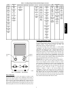
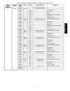
Table 4 – Service Test Modes and Submodes Directory
DISPLAY MENU/
SUB-MENU/
NAME
EXPANDED NAME VALUES
SERVICE TEST
TEST Field Service Test Mode Off/On
INDP Test Independent Outputs
ECON Economizer Position Test 0 to 100
E.CAL Calibrate Economizer Off/On
PE.1 Power Exhaust 1 Test Off/On
PE.2 Power Exhaust 2 Test Off/On
ALRM Alarm Relay Test Off/On
CCH Crankcase Heat Test Off/On
OA.DM OAU 2position Damper Close/Open
WHL OAU Wheel Test 0 to 100
OA.OF OAU OA Fan Speed Test 0 to100
OA.XF OAU PE Fan Speed Test 0 to100
OA.HT OAU Tempring Heater Test 0 to 100
FANS Test Fans
IDF Indoor Fan Power Test Off/On
F.SPD Indoor Fan Speed Test 0 to 100
OFC.1 Outdoor Fan 1 Test Off/On
OFC.2 Outdoor Fan 2 Test Off/On
OFC.3 Outdoor Fan 3 Test Off/On
COOL Test Cooling
CMP.A Cool A Test Off/On
CMP.B Cool B Test Off/On
CMP.C Cool C Test Off/On
F.SPD Reduced Cool Fan Speed 60 to 100
OF.OV Outdoor Fan Override Off/On
HMZR Test Humidi-MiZer
RH1.A Reheat1 A Test Off/On
RH1.B Reheat1 B Test Off/On
RH1.C Reheat1 C Test Off/On
RH2.A Reheat2 A Test Off/On
RH2.B Reheat2 B Test Off/On
RH2.C Reheat2 C Test Off/On
F.SPD Reheat2 Fan Speed 65 to 100
CRC Cool>Reheat1 Valve Test Off/On
RHV.A Reheat2 Valve A Test Off/On
RHV.B Reheat2 Valve B,C Test Off/On
HEAT Test Heating
HT.1 Heat Stage 1 Test Off/On
HT.2 Heat Stage 2 Test Off/On
F.SPD Reduced Heat Fan Speed 65 to 100
48/50PG and PM