


46
Humidi−MiZert Troubleshooting
Use the unit Scrolling Marquee display or a CCN device to view
the cooling status display and the cooling diagnostic display (see
Appendix A) for information on the cooling operation and the
related Humidi-MiZer operation. Check the current alarms and
alarm history for any cooling alarm codes and correct any causes.
(See Table 12.) Verify any unique control configurations per
installed site requirements or accessories.
If alarm conditions are corrected and cleared, operation of the
compressors, fans, and Humidi-MiZer valves may be verified by
using the Service Test mode. (See Table 4.) In addition to general
cooling service analysis (See Table 14), see Table 15 for general
Humidi-MiZer service analysis.
NOTE: Wiring, operation, and charge are different on a
Humidi-MiZer unit compared to a standard unit.
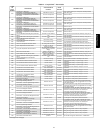
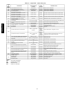
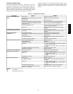
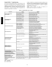
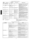
Table 15 – Humidi-MiZer Service Analysis
PROBLEM CAUSE REMEDY
Subcooling Reheat Mode
Will Not Activate.
General cooling mode problem. See Cooling Service Analysis (Table 14).
No dehumidification demand. See No Dehumidification Demand, below.
CRC relay operation. See CRC Relay Operation, below.
Circuit RH1 valve is not open. See RH1 Valve Operation, below.
Circuit CV valve is not closed. See CV Valve Operation, below.
Hot Gas Reheat Mode
Will Not Activate.
General cooling mode problem. See Cooling Service Analysis (Table 14).
No dehumidification demand. See No Dehumidification Demand, below.
CRC relay operation. See CRC Relay Operation, below.
Circuit RH1 valve is not open. See RH1 Valve Operation, below.
Circuit CV valve is not closed. See CV Valve Operation, below.
Circuit RH2 valve is not open. See RH2 Valve Operation, below.
Outdoor temperature too low.
Check Reheat2 Circuit Limit Temperatures
(Configuration→HMZR→RA.LO and RB.LO)
using ComfortLink Scrolling Marquee.
No Dehumidification Demand.
Relative humidity setpoint is
too low — Humidistat
Check/reduce setting on accessory humidistat.
Relative humidity setpoint is
too low — RH sensor.
Check Space RH Setpoints (Setpoints→RH.SP and RH.UN) and
occupancy using ComfortLink Scrolling Marquee.
Software configuration error
for accessory humidistat.
Check Space Humidity Switch (Configuration→
UNIT→RH.SW) using ComfortLink Scrolling Marquee.
Software configuration error
for accessory humidity sensor.
Check RH Sensor on OAQ Input (Configuration→
UNIT→RH.S) using ComfortLink Scrolling Marquee.
No humidity signal. Check wiring. Check humidistat or humidity sensor.
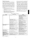
CRC Relay Operation.
No 24V signal to input terminals.
Check using Cool→Reheat1 Valve Test (Service Test→HMZR→CRC)
using ComfortLink Scrolling Marquee.
Check MBB relay output.
Check wiring.
Check transformer and circuit breaker.
No power to output terminals. Check wiring.
Relay outputs do not change state. Replace faulty relay.
CV or RH1 Valve Operation.
(NOTE: Normally Open
When De‐energized)
No 24V signal to input terminals.
Check using Cool→Reheat1 Valve Test (Service Test→HMZR→CRC)
using ComfortLink Scrolling Marquee.
Check CRC Relay Operation.
Check Wiring.
Check transformer and circuit beaker or fuses.
Solenoid coil burnout.
Check continuous over‐voltage is less than 10%.
Check under‐voltage is less than 15%.
Check for missing coil assembly parts.
Check for damaged valve enclosing tube.
Stuck valve. Replace valve. Replace filter drier.
RH2 Valve Operation.
(NOTE: Normally Closed
When De‐energized)
No 24V signal to input terminals.
Check using Cool→Reheat1 Valve Test (Service Test→HMZR→RHV.A or
RHV.B) using ComfortLink Scrolling Marquee.
Check MBB relay output.
Check wiring.
Check transformer and circuit breaker or fuses.
Solenoid coil burnout.
Check continuous over‐voltage is less than 10%.
Check under‐voltage is less than 15%.
Check for missing coil assembly parts.
Check for damaged valve enclosing tube.
Stuck valve. Replace valve. Replace filter drier.
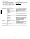
Low Latent Capacity in Subcooling or
Hot Gas Reheat Modes.
CV valve open or leaking. See CV Valve Operation, above.
Low Sensible Capacity in Normal Cool
or Subcooling Reheat Modes.
RH2 valve open or leaking. See RH2 Valve Operation, above.
Low Suction Pressure and High
Superheat During Normal Cool Mode.
General cooling mode problem. See Cooling Service Analysis (Table 14).
RH2 valve open or leaking. See RH2 Valve Operation, above.
Low Suction Pressure
and High Discharge Pressure.
General cooling mode problem. See Cooling Service Analysis (Table 14).
Both RH1 and CV valves closed. See RH1 and CV Valve Operation, above.
RH2 Valve Cycling On/Off.
Hot Gas Reheat mode low suction pressure limit.
Normal Operation During Mixed Circuit Subcooling and Hot Gas Reheat
Modes at Lower Outdoor Temperatures.
Circuit B or C Will Not Operate With
Circuit A Off.
Normal operation. Motormaster outdoor fan con
trol requires operation of circuit A.
None
LEGEND
CRC - Cooling/Reheat Control
CV - Cooling Valve
RH - Relative Humidity
48/50PG and PM