


88
Triple Evacuation Method
The triple evacuation method should only be used when vacuum
pump is capable of pumping down to 28−in. of mercury and
system does not contain any liquid water. Proceed as follows:
1. Pump system down to 28−in. of mercury and allow pump
to continue operating for an additional 15 minutes.
2. Close service valves and shut off vacuum pump.
3. Connect a nitrogen cylinder and regulator to system and
open until system pressure is 2 psig.
4. Close service valve and allow system to stand for 1 hr.
During this time, dry nitrogen will be able to diffuse
throughout the system, absorbing moisture.
5. Repeat this procedure. System will then contain minimal
amounts of contaminants and water vapor.
Refrigerant Charge
Amount of refrigerant charge is listed on unit nameplate. Refer to
Carrier GTAC II; Module 5; Charging, Recovery, Recycling, and
Reclamation section for charging methods and procedures. Unit
panels must be in place when unit is operating during charging
procedure.
Puron (R-410A) refrigerant systems should be charged with
liquid refrigerant. Use a commercial type metering device in the
manifold hose.
UNIT OPERATION AND SAFETY HAZARD
Failure to follow this warning could cause personal
injury, death and/or equipment damage.
Puron (R−410A) refrigerant systems operate at higher
pressures than standard R−22 systems. Do not use R−22
service equipment or components on Puron refrigerant
equipment. Gauge set, hoses, and recovery system must
be designed to handle Puron refrigerant. If unsure
about equipment, consult the equipment manufacturer.
!
WARNING
NOTE: Do not use recycled refrigerant as it may contain
contaminants.
No Charge
Use standard evacuating techniques. After evacuating system,
weigh in the specified amount of refrigerant (refer to unit
nameplate).
NOTE: System charge for units with Humidi-MiZer system is
greater than the system charge of the standard unit.
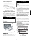
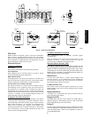
Low Charge Cooling
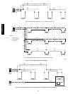
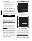
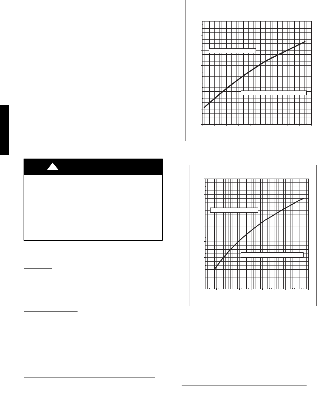
Using cooling charging chart (see Fig. 58−79), add or remove
refrigerant until conditions of the chart are met. An accurate
pressure gauge and temperature-sensing device is required.
Charging is accomplished by ensuring the proper amount of liquid
subcooling. Connect pressure gauge to the compressor discharge
service valve. Connect temperature sensing device to the liquid
line between the condenser and the TXV (thermostatic expansion
valve), and insulate it so that ambient temperature does not affect
reading.
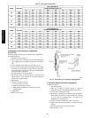
To Use the Cooling Charging Chart, Standard Unit
NOTE: All circuits must be running in normal cooling mode.
Indoor airflow must be within specified air quantity limits for
cooling. (See Appendix D.) All outdoor fans must be on and
running at high speed. Use the Cooling Service Test Outdoor Fan
Override function to start all outdoor fans.
R410A
R410A
REFRIGERA
REFRIGERA
NT
NT
OUTDOOR
OUTDOOR
FAN
FAN
MUST
MUST
BE
BE
OPERATING
OPERATING
ON
ON
HIGH
HIGH
SPEED
SPEED
20
20
40
40
60
60
80
80
100
100
120
120
140
140
160
160
150
150
200
200
250
250
300
300
350
350
400
400
450
450
500
500
550
550
600
600
Comp
Comp
ressor
ressor
Disch
Disch
arge
arge
Pressu
Pressu
re,
re,
[p
[p
sig
sig
]
Outdoor
Outdoor
Coil
Coil
L
eavin
eavin
g Te mp
Temp
eratu
eratu
re,
re,
[Deg
[Deg
rees
rees
F]
F]
Add
dd
Charge
Charge
if
if
Above
bove
the
the
Curve
Curve
Remo
Remo
ve
ve
Charge
Charge
if
if
Below
Below
the
the
Curve
Curve
C07038
Fig. 58 − Charging Chart — 48/50PG03
R4
R4
10A RE
RE
FRI
RI
GERANT
RANT
OUTDOORF
R F
ANM
N M
UST BE OPERATING ONH
N H
IGHS
H S
PEED
20
20
40
40
60
60
80
80
10
10
0
12
12
0
14
14
0
16
16
0
150
150
200
200
250
250
300
300
350
350
400
400
450
450
500
500
550
550
600
600
Compress
ss
or Disc
isc
harge Press
ss
ure, [psig
sig
]
Add Cha
ha
rge
ge
if Abov
bov
e the
the
Cur
ur
ve
Re
Re
move Charge if Be
Be
low the Curve
Outdoor
Outdoor
Coil
Coil
Leavin
eavin
g Te mp
Temp
eratu
eratu
re,
re,
[Deg
[Deg
rees
rees
F]
F]
C07039
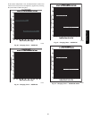
Fig. 59 − Charging Chart — 48/50PG04
Use the temperature and pressure readings, and find the
intersection point on the cooling charging chart. If intersection
point on chart is above line, add refrigerant. If intersection point on
chart is below line, carefully recover some of the charge. Recheck
suction pressure as charge is adjusted.
The TXV is set to maintain between 10 and 15 degrees of
superheat at the compressors. The valves are factory set and cannot
be adjusted. Do not use A TXV designed for use with R-22.
To Use the Cooling Charging Charts, Units With
Humidi−Mizert Adaptive Dehumidification System
NOTE: All circuits must be running in normal cooling mode.
Indoor airflow must be within specified air quantity limits for
cooling. (See Appendix D.) All outdoor fans must be on and
running at high speed. Use the Cooling Service Test Outdoor Fan
function (Service Test→COOL→OF.OV) to start all outdoor fans.
48/50PG and PM