


14
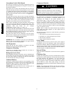
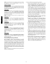
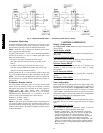
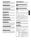
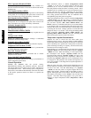
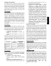
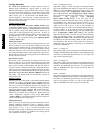
FS.SW = 1 (NO)
FS.SW = 2 (NC)
C09346
Fig. 8 − 48PG/PM Humidi−MiZert − Third Party Smoke Detector Wiring
Economizer Monitoring
On field terminal board (TB1), terminals 8, 9, and 10 can be used
to monitor economizer position from a third party control system.
See economizer operation section for additional information.
NOTE: Terminal 8 will not represent economizer position if the
unit is equipped with Adaptive Fan.
In digital mode (E.CTL = 1 or 2), the economizer commanded
position can be read as a 2−10v or 4−20mA signal. TB1−8 and
TB1−9 are used as follows:
To read a 2−10v signal, disconnect the violet wire on
TB1−J10−8 and place volt meter device across TB1−8 and
TB1−9.
To read a 4−20mA signal, disconnect the violet wire on
TB1−J10−8 and the 500Ω resister at TB1−J10−6. Place amp
meter device between TB1−8 and TB1−9.
In analog mode (E.CTL = 3), the economizer position can be read
as a 2−10v feedback signal across TB1−10 and TB1−9 at any time.
NOTE: The violet wire and 500Ω resister must be connected at
the J10 connector as originally wired to operate the economizer in
analog mode.
Economizer Damper Control
For units with the economizer option or accessory and the ECB
control board, the damper position can be directly controlled
through the IAQ sensor input provided on the field connection
terminal board. The IAQ Analog Input configuration,
Configuration→AIR.Q→IA.CF will have to set to 3 (Control
Minimum Position). When IA.CF = 3, an external 4 to 20 mA
source is used to move the damper 0% to 100% directly.
Terminal 2 = 4−20mA + signal
Terminal 3 = 4−20mA − common
NOTE: In this mode, preset minimum positions configurations are
not valid, the damper position may exceed the input position to
provide economizer cooling and CO
2
sensor input can not be used
for DCV control. Refer to the Indoor Air Quality operation section
for more information.
CONTROLS OPERATION
Display Configuration
The Configuration→DISP submenu is used to configure the local
display settings.
Metric Display (METR)
This variable is used to change the display from English units to
Metric units.
Language Selection (LANG)
This variable is used to change the language of the ComfortLink
display. At this time, only English is available.
Password Enable (PROT)
This variable enables or disables the use of a password. The
password is used to restrict use of the control to change
configurations.
Service Password (PSWD)
This variable is the 4-digit numeric password that is required if
enabled.
Test Display LEDs (TEST)
This is used to test the operation of the ComfortLink display.
Unit Configuration
Many configurations that indicate what factory options and/or field
accessories are installed and other common operation variables are
included in Unit Configuration (Configuration→UNIT). These
configurations will be set in the factory for the factory−installed
options (FIOPs). Field−installed accessories installed will require
configuration changes. General unit and fan control configurations
are also covered under this Unit Configuration menu.
Start−Up Delay (S.DLY)
This configuration sets the control start-up delay after the power is
interrupted. This can be used to stagger the start-up of multiple
units.
Unit Control Type (U.CTL)
This configuration defines if temperature control is based on
thermostat inputs or space temperature sensor input.
U.CTL = 2 (Thermostat) – The unit determines cooling and
heating demand by the state of G, Y1, Y2, W1, and W2 inputs
from a space thermostat. This value is the factory default.
U.CTL = 3 (Space Sensor) – The unit determines cooling and
heating demand based on the space temperature and the
appropriate set point. Used also as Linkage configuration. The
jumper wire in the installer’s packet must be connected between
R and W1 on the low voltage terminal board (TB) for heating
mode to operate.
48/50PG and PM