


15
Thermostat Control Type (T.CTL)
This configuration applies only if Unit Control Type is Thermostat
(Configuration→Unit→U.CTL = 2). The value determines
alternative cooling and Humidi-MiZer circuit staging. See the
Cooling and Humidi-MiZer sections for more information. The
factory default value is T.CTL = 0 (Adaptive).
Fan On When Occupied (OC.FN)
This configuration applies only if Unit Control Type is Space
Sensor (Configuration →Unit→U.CTL = 3). A YES value will
operate the indoor fan whenever the unit is in the Occupied mode.
A NO value will operate the indoor fan only when heating or
cooling is necessary. The factory default value is YES.
Shut Down on IDF Failure (IDF.F)
This configuration applies only if a fan switch is installed and
configured. A YES value will enable diagnostic Alert T409 to shut
down the unit when incorrect fan status is sensed. A NO value will
still permit Alert T409 but will not cause unit shutdown. The
factory default value is YES.
Fan Status Switch (FN.SW)
This configuration identifies if a fan status switch is installed, and
what status (normally open, normally closed) the input is when the
indoor fan is OFF.
Filter Status Switch (FL.SW)
This configuration identifies if a filter status switch is installed, and
what status (normally open, normally closed) the input is when the
filter is CLEAN.
Fire Shutdown Switch (FS.SW)
This configuration identifies if a fire shutdown switch is installed,
and what status (normally open, normally closed) the input is when
the fire or smoke alarm is OFF (no alarm).
Remote Occupancy Switch (RM.SW)
This configuration identifies if a remote occupancy switch is
installed, and what status (normally open, normally closed) the
input is when UNOCCUPIED.
SAT Settling Time (SAT.T)
This configuration sets the settling time of the supply air
temperature (SAT). This tells the control how long to wait after a
stage change before trusting the SAT reading. See Adaptive
Thermostat Control (U.CTL = 2, T.CTL = 0) and Space Sensor
Control (U.CTL = 3) within the Cooling operation section for
more information. The factory default value is 240 seconds.
RAT Sensor On SPTO Input (RAT.S)
This configuration identifies if a return air temperature (RAT)
sensor is installed on the space temperature offset (SPTO) input. A
YES value enables RAT display. A NO value disables RAT
display. Installing an RAT sensor will allow economizer differential
dry bulb control. Refer to the economizer operation for more
information.
RH Sensor On OAQ Input (RH.S)
This configuration identifies if a space relative humidity sensor is
installed on the outdoor air quality (OAQ) input. A YES value
enables SP.RH display. If a Humdi-MiZer unit, then the unit
determines dehumidification demand based on this input and the
appropriate set point. A NO value disables SP.RH display and use.
Space Humidity Switch (RH.SW)
This configuration identifies if a space relative humidity switch is
installed on the ENTHALPY input, and what status (normally
open, normally closed) the input is when the space humidity is
LOW.
Temperature Compensated Start Cooling Factor
(TCS.C)
This factor is used in the equation of the Temperature
Compensated Start Time Bias for cooling. A setting of 0 minutes
indicates Temperature Compensated Start in Cooling is not
permitted.
Temperature Compensated Start Heating Factor
(TCS.H)
This factor is used in the equation of the Temperature
Compensated Start Time Bias for heating. A setting of 0 minutes
indicates Temperature Compensated Start in Heating is not
permitted.
Modes
The ComfortLink controls operate under a hierarchy of
command structure as defined by four main elements: the System
Mode, the HVAC Mode, the Occupied status, and the Unit Control
Type.
The System Mode is the top level that defines three main states of
the control system: Disabled, Enabled, or Test.
The HVAC Mode is the next level that defines four main states of
functional operation: Disabled, Fan Only, Cool, and Heat.
The Occupied status affects set points for cooling and heating in
Space Sensor control mode and operation of the economizer for
indoor air quality ventilation and free cooling.
The Unit Control Type (Configuration→UNIT→U.CTL) defines
if temperature control is based on thermostat inputs or space
temperature sensor input.
The general operating mode of the control and the status of some
related operation lockouts are located on the display at two
locations: Run Status→ MODE and Operating Modes→ MODE.
System Mode (SYS)
In Run Status and Operating Modes, the current system mode is
displayed with expandable text. This is an overall state of the unit.
Three states are: Unit Operation Disabled, Unit Operation Enabled,
or Service Test Enabled.
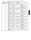
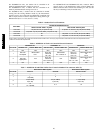
HVAC Mode (HVAC)
In Run Status and Operating Modes, the current allowed HVAC
mode is displayed with expandable text. This is the mode the unit
decides to run in based on its inputs. There are four main HVAC
modes; cooling has six different expanded texts. These modes are
shown below.
HVAC
Mode
Expanded Text Brief Description
Disabled HVAC Operation
Disabled
Unit is in test mode or System mode
is disabled
Fan Only Ventilation (fan-
only)
Fan may run for ventilation
Cooling
Cooling Mechanical cooling
Free Cooling Only economizer used for cooling
Unoccupied Free
Cooling
Only economizer use for cooling
(occupied cooling set point active)
Reheat1 All running circuits in sub-cooling
mode
Reheat2 All running circuits in Hot Gas Reheat
mode
Reheat1/Reheat2 Sub-cooling and Hot Gas Reheat
active
Heating Heating Heating mode
48/50PG and PM