


20
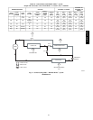
For 48/50PG03−07 units, one outdoor fan is controlled in all
modes by the Motormaster sensing on circuit A.
For 48/50PG08−14 units, 2 outdoor fans are controlled in all
modes by the Motormaster sensing on circuit A.
For 48/50PG16 units, 3 outdoor fans are controlled in normal
cooling and sub−cooling Reheat1 modes by the Motormaster
sensing circuit A. Two of the fans are additionally controlled with
OFC.1 output, based on outdoor temperature, during the hot−gas
Reheat2 mode (level 1 = 1 fan, level 2 = 3 fans).
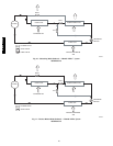
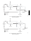
For 48/50PG20−28 and 48/50PM16−28 units, contactor OFC1
controls power to the Motormaster which controls OFM1 and
OFM4. Contactor OFC2 controls the remaining two fans (16 and
20 size) or remaining 4 fans (24 and 28 sizes).
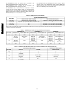
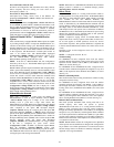
Table 5 – Outdoor Fan Level Transitions
FAN LEVEL
OUTDOOR TEMPERATURE (F)
Without Humidi-MiZer™ System With Humidi-MiZer System
Level 2 On 55 (sizes 03-20), 45 (sizes 24-28) 61 (PG03-16, sizes 24-28), 68 (size 20, PM16)
Level 2 Off 45 (PG03-16), 50 (size 20, PM16), 40 (sizes 24-28) 57
Level 3 On 65 68 (PG03-16, size 24-28), 88 (size 20, PM16)
Level 3 Off 55 62 (PG03-16, size 24-28), 78 (size 20, PM16)
NOTE: Where not specified, the models are both PG and PM. Levels 0 and 1 are only in play if the OAT is lower than the Level 2 On temperature and the
pressure is not above its respected max.
Table 6 – 48/50PG03−16 Fan Level Control of Fans and Contactors
FAN LEVEL
48/50PG03-07 48/50PG08-14 48/50PG16
Standard Unit Humidi-MiZer Unit Standard Unit Humidi-MiZer Unit Standard Unit Humidi-Mizer Unit
0 OFF OFF OFF OFF OFF OFF
1
OFC1 On
Low Speed
Motormaster
Fan 1
OFC1 On,
OFC2 Off
Fan 1 On
Motormaster
Fan 1 and Fan 2
OFC1 On,
OFC2 Off
Fan 1 On
Motormaster, OFC1
Off
Fan 2
2
OFC1 Off
High Speed
N/A
OFC1 On,
OFC2 On
Fan 1 and 2 On
N/A
OFC1 On,
OFC2 On
Fan 1, 2, 3 On
Motormaster, OFC1
On
Fan 1, 2, 3
3 N/A N/A N/A N/A N/A N/A
Table 7 – 48/50PG20−28 and PM16−28 Fan Level Control of Outdoor Fan contactors (OFC(X))
FAN LEVEL
With Humidi-MiZer System With Humidi-MiZer System
Circuit A Circuit B Circuit A and B
0 - - -
1
1
1, 3 (PG28)
3 1
2
1,2 (20, PM16)
2 (24-28)
2, 3 (20, PM16)
2 (24-28)
1, 2 (20, PM16)
2 (24-28)
3
1,2
1, 2, 3 (PG28)
2, 3 1, 2
48/50PG and PM