


19
Space Sensor Control
Space sensor staging control is an adaptive anticipation control that
weighs the actual space demand against the trend of that demand
and the trend of the supply air. It also honors stage time guards
and supply air limits. The demand for cooling in the space is
displayed as the Cooling Demand (Run Status→COOL
→DMD.C). The control tries to anticipate the change in the space
because of its current stage status. This anticipation is based on the
Supply−Air Trend (Operating Modes→COOL→SA.TR) and the
Cool Demand Trend (Operating Modes→COOL→TRD.C).
These trends will show the control how the space is reacting to the
current running conditions and help it decide when to add or
remove one stage from the requested stages. The Cool Stage
Increase Time (Configuration→COOL→C.INC) or the Cool
Stage Decrease Time (Configuration→COOL→C.DEC) has to
expire before another stage can be added or a stage can be
subtracted. If at any time the Supply−Air Temperature (SAT) falls
below the Minimum Supply Air Temperature Upper Level
(Configuration→COOL→SAT→SAT.U), the requested stages
will not be allowed to increase. If at any time the SAT falls below
the Minimum Supply Air Temperature Lower Level
(Configuration→COOL→SAT→SAT.L), the requested stages will
be reduced by one without honoring C.DEC. If SAT.L and SAT.U
are configured so that they are close together, the last stage of
compressor might cycle rapidly, slowed only by its minimum on
and off−time requirements.
Compressor Control
The compressor control works hand and hand with the staging
control. As the staging control requests stages, the compressor
control determines what actual compressors are available or
running and tries to provide stages for what is requested. The
availability of a compressor depends on time guards, circuit
diagnostics, outdoor temperature, and the unit size.
The Number of Circuits (Configuration→COOL→N.CIR)
configuration tells the control how many compressors are installed
on the unit. The Circuit A Lockout Temp
(Configuration→COOL→CIR.A →CA.LO), Circuit B Lockout
Temp (Configuration→COOL →CIR.B→CB.LO), and Circuit C
Lockout Temp (Configuration →COOL→CIR.C→CC.LO)
configurations set the outdoor temperature in which the respective
compressor is allowed to run down to. Timeguard A (Run
Status→COOL→CIR.A→TG.A), Timeguard B (Run
Status→COOL→CIR.B→TG.B), and Timeguard C (Run
Status→COOL→CIR.C→TG.C) display the time a respective
compressor has before it is available for use. Individual circuit
diagnostic tests are performed during operation which may or may
not allow a compressor to be used. The configuration point
Compressors On Circuit A (Configuration →COOL→N.A)
informs the control to run diagnostics on one or two compressors
for circuit A. The available stages at any given time are displayed
as Available Compressors (Run Status→COOL →AVL.C). The
actual compressors running at any given time are displayed as
Actual Cooling Stages (Operating Modes→COOL →ACT.C).
Compressor A (Run Status→COOL→CIR.A →CMP.A),
Compressor B (Run Status→COOL→CIR.B →CMP.B), and
Compressor C (Run Status→COOL→CIR.C →CMP.C) are
displayed on when the respective compressor is running.
There are time guards to protect the compressors. Compressor Min
On Time (Configuration→COOL→MRT.C) and Compressor Min
Off Time (Configuration→COOL→MOT.C) apply before a
compressor can be turned back on or turned off.
Outdoor Fan Control
Each unit has a means for variable outdoor airflow to control
condenser pressure control within an acceptable range by
responding to varied operating modes and ambient temperatures.
This is implemented differently on different units using
multi−speed motors, multiple outdoor fans, or variable−speed
motor controllers.
NOTE: Factory default configurations account for these model
differences and should not be changed. The default configurations
have been qualified over a large range of conditions and are
provided in case a field replacement of a control board occurs and
the settings need to be checked or manually configured. Outdoor
fan operation is further described below to assist in
troubleshooting.
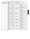
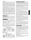
The outdoor fans are controlled by levels. There are 4 levels of
operation (0−3) and the current operating level is shown as
Outdoor Fan Level (Operating Modes→COOL→F.LEV). The
fan level selected during operation is based on factory
configurations of outdoor temperature limits and condenser
pressure limits. These are in the Outdoor Fan Control submenu
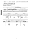
(Configuration→COOL→OFC) and shown in Table 5. The
starting level is picked after a compressor is turned on and is based
on the Outdoor Air Temperature (Temperatures→AIR.T→OAT).
A circuit’s Saturated Condensing Temperature (Temperatures
→REF.T→SCT.x) can override the fan level at any time if the
specific Fan Level Max Pressure (Configuration→COOL→OFC
→x.MXP) is exceeded. This override will end if the circuit’s
saturated condensing temperature (SCT) drops below the specific
Fan Level Min Pressure (Configuration→COOL→OFC
→x.MNP). The number of fans and contactors on at a given fan
level depends on the specific unit options and size. See Tables 6
and 7 and below text for specific fan and contactor status at any
given fan level.
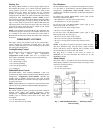
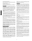
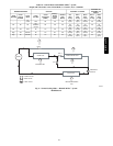
Units Without Humidi−MiZert System
Outdoor Fan Motors (OFM) are controlled by Outdoor Fan
Contactors (OFC) which are controlled by the main base board
(MBB).
For 48/50PG03−07 units, a duel speed motor is used. The
Compressor Contactor (C.A1) turns the OFM on in high speed and
the OFC1 is used to change to low speed.
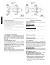
For 48/50PG08−14 units, OFM1 is controlled by OFC1 and
OFM2 is controlled by OFC2.
For 48/50PG16 units, OFM1 is controlled by OFC1 and OFM1
and 2 are controlled by OFC2.
For 48/50PG20−28 and 48/50PM16−28 units, OFM1 is controlled
by OFC1, OFM4 is controlled by OFC3, and OFC2 controls the
remaining two fans (16 and 20 size) or remaining 4 fans (24 and 28
sizes).
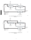
Units With Humidi−MiZer System
Outdoor fan control for Humidi−MiZer units includes a
Motormaster variable−speed control of some or all outdoor fans,
depending on unit size. The Motormaster control automatically
adjusts the outdoor fan speed to maintain approximately 80 to
100F condenser temperature for circuit A at all outdoor ambient
temperatures. Some unit sizes have additional on/off staging of
some outdoor fans. The fan level operation is determined by some
or all Outdoor Fan Control configurations described above, plus
additional Humidi−MiZer Configuration (Configuration
→HZMR). Refer to the Humidi−MiZer operation section for
details on the Reheat function fan control.
48/50PG and PM