


75
Integrated Gas Control (IGC) Board
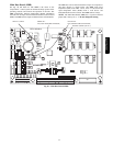
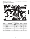
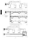
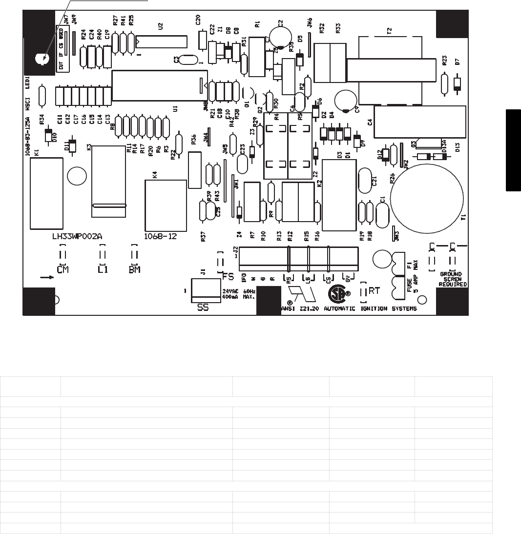
The IGC is provided on gas heat units. (See Fig. 42 and Table 25.)
The IGC controls the direct spark ignition system and monitors the
rollout switch, limit switch, and induced-draft motor Hall Effect
switch.
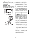
The IGC is equipped with an LED (light-emitting diode) for
diagnostics. See the Troubleshooting section for more information.
RED LED-STATUS
C07028
Fig. 42 − Integrated Gas Control (IGC) Board
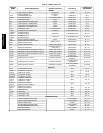
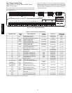
Table 25 – IGC Connections
TERMINAL
LABEL
POINT DESCRIPTION SENSOR LOCATION TYPE OF I/O
CONNECTION
PIN NUMBER
INPUTS
RT, C Input power from TRAN 1 control box 24 VAC
SS Speed sensor gas section analog input J1, 1-3
FS, T1 Flame sensor gas section switch input
W Heat stage 1 MBB 24 VAC J2, 2
RS Rollout switch gas section switch input J2, 5-6
LS Limit switch gas section switch input J2, 7-8
CS Centrifugal switch (not used) switch input J2, 9-10
OUTPUTS
L1, CM Induced draft combustion motor gas section line VAC
IFO Indoor fan request control box relay J2, 1
GV (W1) Gas valve (heat stage 1) gas section relay J2, 12
GV (W2) Gas Valve (heat stage 2, from MBB) gas section Not on IGC
48/50PG and PM