


10
NOTE: On standard units, the fire shutdown input is the terminals
Fire Shutdown 1 and 2. On Humidi-MiZer units, the fire
shutdown connections are at PL19.
Outdoor Enthalpy
If an Outdoor Enthalpy accessory was field installed, the unit must
be configured for it by setting Configuration→ECON→EN.SW,
identifies the normally open or normally closed status of this input
when the outdoor enthalpy is low.
IAQ Switch
If an IAQ Switch accessory was field installed, the unit must be
configured for it by setting Configuration→AIR.Q→II.CF,
identifies the normally open or normally closed status of this input
when the indoor air quality value is low (good) and also selects the
unit response to this input.
NOTE: An IAQ switch cannot be used if an enthalpy switch is
already on this input.
IAQ Sensor
If an CO
2
Sensor accessory was field installed, the unit must be
configured for it by setting Configuration→AIR.Q→IA.CF
selects the unit response to this input. Default conversion to 0 to
2000 ppm.
OAQ Sensor
If an Outdoor Air Quality Sensor accessory was field installed, the
unit must be configured for it by setting Configuration→AIR.Q
→OA.CF selects the unit response to this input. Default
conversion to 0 to 2000 ppm.
Fan Status
If a Fan Status accessory was field installed, the unit must be
configured for it by setting Configuration→UNIT→FN.SW to
normally open (1) or normally closed (2). Normally open (1) is the
preferred configuration.
NOTE: Fan Status input is not on the terminals marked Fan
Status.
Filter Status
If a Filter Status accessory was field installed, the unit must be
configured for it by setting Configuration→UNIT→FL.SW to
normally open (1) or normally closed (2). Normally open (1) is the
preferred configuration.
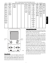
Programming Operating Schedules
The ComfortLink controls will accommodate up to eight
different schedules (Periods 1 through 8), and each schedule is
assigned to the desired days of the week. Each schedule includes
an occupied on and off time. As an example, to set an occupied
schedule for 8 AM to 5 PM for Monday through Friday, the user
would set days Monday through Friday to ON for Period 1. Then
the user would configure the Period 1 Occupied From point to
08:00 and the Period 1 Occupied To point to 17:00. To create a
different weekend schedule, the user would use Period 2 and set
days Saturday and Sunday to ON with the desired Occupied On
and Off times.
NOTE: By default, the time schedule periods are programmed for
24 hours of occupied operation.
To create a schedule, perform the following procedure:
1. Scroll to the Configuration mode, and select CCN
CONFIGURATION (CCN). Scroll down to the Schedule
Number (Configuration→CCN→SCH.O=SCH.N). If
password protection has been enabled, the user will be
prompted to enter the password before any new data is
accepted. SCH.N has a range of 0 to 99. The default value
is 1. A value of 0 is always occupied, and the unit will
control to its occupied set points. A value of 1 means the
unit will follow a local schedule, and a value of 65 to 99
means it will follow a CCN schedule. Schedules 2−64 are
not used as the control only supports one internal/local
schedule. If one of the 2−64 schedules is configured, then
the control will force the number back to 1. Make sure the
value is set to 1 to use a local schedule.
2. Enter the Time Clock mode. Scroll down to the LOCAL
TIME SCHEDULE (SCH.L) sub−mode, and press
ENTER. Period 1 (PER.1) will be displayed.
3. Scroll down to the MON.1 point. This point indicates if
schedule 1 applies to Monday. Use the ENTER command
to go into Edit mode, and use the Up or Down key to
change the display to YES or NO. Scroll down through the
rest of the days and apply schedule 1 where desired. The
schedule can also be applied to a holiday.
4. Configure the beginning of the occupied time period for
Period 1 (OCC). Press ENTER to go into Edit mode, and
the first two digits of the 00.00 will start flashing. Use the
Up or Down key to display the correct value for hours, in
24−hour (military) time. Press ENTER and hour value is
saved and the minutes digits will start flashing. Use the
same procedure to display and save the desired minutes
value.
5. Configure the unoccupied time for period 1 (UNC). Press
ENTER to go into Edit mode, and the first two digits of the
00.00 will start flashing. Use the Up or Down key to display
the correct value for hours, in 24−hour (military) time. Press
ENTER and hour value is saved and the minutes digits will
start flashing. Use the same procedure to display and save
the desired minutes value.
6. The first schedule is now complete. If a second schedule is
needed, such as for weekends or holidays, scroll down and
repeat the entire procedure for period 2 (PER.2). If
additional schedules are needed, repeat the process for as
many as are needed. Eight schedules are provided. See
Table 3 for an example of setting the schedule.
48/50PG and PM