


77
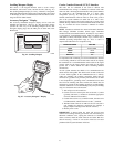
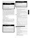
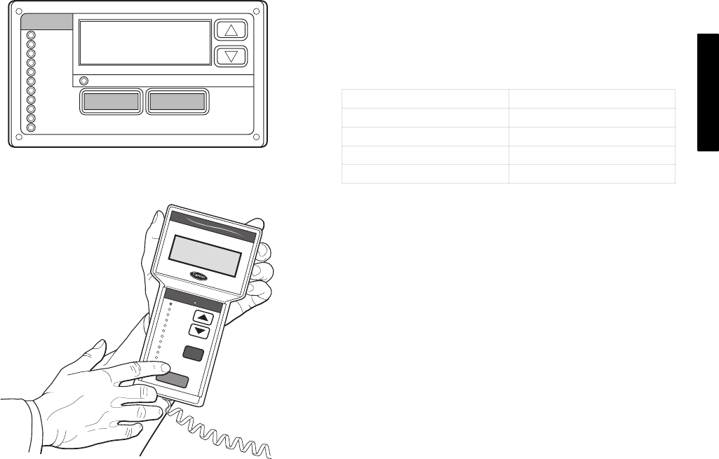
Scrolling Marquee Display
This device is the keypad interface used to access rooftop
information, read sensor values, and test the unit. (See Fig. 44.)
The Scrolling Marquee display is a 4-key, 4-character, 16-segment
LED (light-emitting diode) display. Eleven mode LEDs are located
on the display as well as an Alarm Status LED. See Basic Control
Usage section for further details.
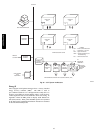
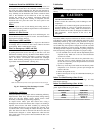
Accessory Navigatort Display
The accessory hand-held Navigator display can be used with
48/50PG and PM units. (See Fig. 45.) The Navigator display
operates the same way as the Scrolling Marquee device. The
Navigator display plugs into the LEN port on either TB or the
ECB board.
Run Status
Service Test
Temperature
Pressures
Setpoints
Inputs
Outputs
Configuration
Time Clock
Operating Modes
Alarms
Alarm Status
ENTER
MODE
ESCAPE
C06320
Fig. 44 − Scrolling Marquee
Ru
n Sta
tu
s
S
e
rv
ice
Te
s
t
T
em
p
era
ture
s
P
res
s
ure
s
S
e
tpo
in
ts
In
pu
ts
O
utp
uts
C
on
fig
u
ra
tion
T
im
e C
lo
ck
O
p
er
ating
M
od
es
A
la
rm
s
E
N
T
E
R
E
S
C
M
O
D
E
Ala
rm
Sta
tus
T
IM
E
E
W
T
L
W
T
S
E
T
P
1
2
.
5
8
5
4
.
6
°
F
4
4
.1
°
F
4
4
.
0
°
F
N
A
V
I
G
A
T
O
R
C
o
m
f
o
r
tL
in
k
C06321
Fig. 45 − Accessory Navigatort Display
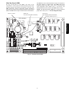
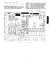
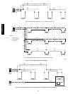
Carrier Comfort Network (CCN)R Interface
The units can be connected to the CCN if desired. The
communication bus wiring is a shielded, 3-conductor cable with
drain wire and is field supplied and installed. The system elements
are connected to the communication bus in a daisy chain
arrangement. (See Fig. 46.) The positive pin of each system
element communication connector must be wired to the positive
pins of the system elements on either side of it. This is also
required for the negative and signal ground pins of each system
element. Wiring connections for CCN should be made at TB. (See
Fig. 18.) Consult the CCN Contractor’s Manual for further
information.
NOTE: Conductors and drain wire must be 20 AWG (American
Wire Gauge) minimum stranded, tinned copper. Individual
conductors must be insulated with PVC, PVC/nylon, vinyl, Teflon,
or polyethylene. An aluminum/polyester 100% foil shield and an
outer jacket of PVC, PVC/nylon, chrome vinyl, or Teflon with a
minimum operating temperature range of –20C to 60C is
required. See Table below for acceptable wiring.
MANUFACTURER PART NO.
Alpha 2413 or 5463
Belden 8772
Carol C2528
West Penn 302
It is important when connecting to a CCN communication bus that
a color-coding scheme be used for the entire network to simplify
the installation. It is recommended that red be used for the signal
positive, black for the signal negative and white for the signal
ground. Use a similar scheme for cables containing different
colored wires.
At each system element, the shields of its communication bus
cables must be tied together. The shield screw on TB1 can be used
to tie the cables together. If the communication bus is entirely
within one building, the resulting continuous shield must be
connected to a ground at one point only. The shield screw on TB1
is not acceptable for grounding. If the communication bus cable
exits from one building and enters another, the shields must be
connected to grounds at the lightning suppressor in each building
where the cable enters or exits the building (one point per building
only). To connect the unit to the network:
1. Turn off power to the control box.
2. Cut the CCN wire and strip the ends of the red (+), white
(ground), and black (–) conductors. (Substitute appropriate
colors for different colored cables.)
3. Connect the red wire to (+) terminal on TB1, the white wire
to COM terminal, and the black wire to the (–) terminal.
4. The RJ14 CCN connector on TB1 can also be used, but is
only intended for temporary connection (for example, a
laptop computer running Carrier network software).
5. Restore power to unit.
IMPORTANT: A shorted CCN bus cable will prevent some
routines from running and may prevent the unit from starting. If
abnormal conditions occur, unplug the connector. If conditions
return to normal, check the CCN connector and cable. Run new
cable if necessary. A short in one section of the bus can cause
problems with all system elements on the bus.
48/50PG and PM