


87
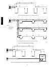
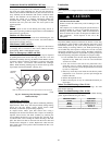
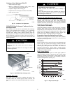
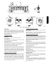
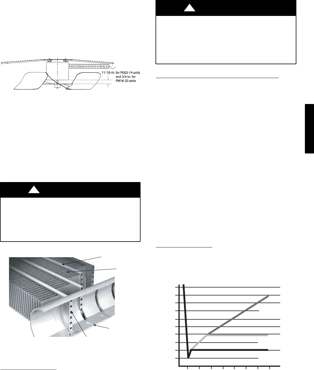
Condenser-Fan Adjustment (Fig. 55)
1. Shut off unit power supply.
2. Remove condenser-fan assembly (grille, motor, motor
cover, and fan) and loosen fan hub setscrews.
3. Adjust fan height as shown in Fig. 55.
4. Tighten setscrews and replace condenser-fan assembly.
5. Turn on power to unit.
C09292
Fig. 55 − Condenser−Fan Adjustment
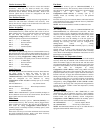
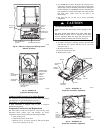
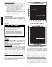
NOVATION Heat Exchanger Condenser Service
and Replacement
The condenser coil in this unit is a NOVATION heat exchanger
surface. The NOVATION heat exchanger is an all−aluminum
construction with fins over a single−depth crosstube. The
crosstubes have multiple small passages through which the
refrigerant passes from header to header on each end. (See Fig. 56.)
The all−aluminum construction provides increased resistance to
corrosion over aluminum fins on copper tubes in normal and mild
marine applications.
EQUIPMENT DAMAGE HAZARD
Failure to follow this caution may result in damage to
equipment.
Refer to product data manual for coil usage in coastal or
industrial applications.
CAUTION
!
TUBES
FINS
MICROCHANNELS
MANIFOLD
a30-4457
C07273
Fig. 56 − NOVATION Heat Exchanger Coils
Repairing Tube Leaks
RCD offers service repair kits for repairing tube leaks in the
crosstubes. These kits include approved braze materials and
instructions specific to the aluminum NOVATION heat exchanger
coil.
EQUIPMENT DAMAGE HAZARD
Failure to follow this caution may result in damage to
equipment.
Use of other than approved repair procedures may affect the
pressure rating or the corrosion resistance of the NOVATION
heat exchanger condenser coil.
CAUTION
!
Replacing the NOVATION Heat Exchanger Coil
The service replacement coil is preformed and is equipped with
transition joints with copper stub tubes. When brazing the
connection joints to the unit tubing, use a wet cloth around the
aluminum tube at the transition joint. Avoid applying torch flame
directly onto the aluminum tubing.
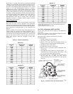
Verify Sensor Performance
Verify that thermistor, transducer, and switch inputs are reading
correctly. These values can be accessed through the Scrolling
Marquee display in the Temperatures, Pressures, and Inputs menus.
Some values will depend on configuration choices. Refer to the
Control Set Up Checklist completed for the specific unit
installation and to the configuration tables in Appendix A.
Economizer Operation During Power Failure
Dampers have a spring return. In event of power failure, dampers
will return to fully closed position until power is restored. Do not
manually operate damper motor.
Evacuation
Proper evacuation of the system will remove noncondensables and
ensure a tight, dry system before charging. Evacuate from both
high and low side ports. Never use the system compressor as a
vacuum pump. Refrigerant tubes and indoor coil should be
evacuated to 500 microns. Always break a vacuum with dry
nitrogen. The two possible methods are the deep vacuum method
and the triple evacuation method.
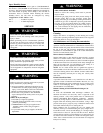
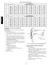
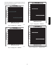
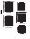
Deep Vacuum Method
The deep vacuum method requires a vacuum pump capable of
pulling a minimum vacuum of 500 microns and a vacuum gauge
capable of accurately measuring this vacuum depth. The deep
vacuum method is the most positive way of assuring a system is
free of air and liquid water. (See Fig. 57.)
LEAK IN
SYSTEM
VACUUM TIGH
T
TOO WET
TIGHT
DRY SYSTEM
0
1
2
3
4
56
7
MINUTES
5000
4500
4000
3500
3000
2500
2000
1500
1000
500
MICRONS
C06264
Fig. 57 − Deep Vacuum Graph
48/50PG and PM