


8
Condenser Fans and Motors
Condenser fans and motors are factory set. Refer to Condenser-Fan
Adjustment section as required.
Return−Air Filters
Check that correct filters are installed in filter tracks (see Physical
Data table in Installation Instructions). Do not operate unit without
return-air filters.
NOTE: For units with 4-in. filter option, units are shipped with
standard 2-in. filters. To install 4-in. filters, the filter spacers must
be removed.
Outdoor−Air Inlet Screens
Outdoor-air inlet screens must be in place before operating unit.
Air Baffles
Units with Humidi-MiZer option are equipped with
Motormaster control to maintain adequate discharge pressure for
proper unit operation during low ambient operation.
Field-fabricated and installed wind baffles may be required. See
Optional Humidi-MiZer Dehumidification System section.
Accessory Installation
Check to make sure that all accessories including space thermostats
and sensors have been installed and wired as required by the
instructions and unit wiring diagrams.
Orifice Change (48PG and 48PM)
This unit is factory assembled for heating operation using natural
gas at an elevation from sea level to 2000 ft.
Use accessory high altitude kit when installing this unit at an
elevation of 2000 to 7000 ft. For elevations above 7000 ft, refer to
High Altitude section to identify the correct orifice size for the
elevation. Purchase these orifices from your local Carrier dealer.
Follow instructions in accessory Installation Instructions to install
the correct orifices.
Use accessory LP (liquid propane) gas conversion kit when
converting this unit for use with LP fuel usage for elevations up to
7000 ft. For elevations above 7000 ft, refer to High Altitude
section to identify the correct orifice size for the elevation.
Purchase these orifices from your local Carrier dealer. Follow
instructions in accessory Installation Instructions to install the
correct orifices.
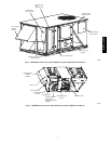
Gas Heat (48PG and 48PM)
Inspect the gas heat section of the unit. Verify the number of
burners match the number of heat exchanger openings and the
burner assembly is properly aligned. If the orifices were changed
out for elevation or Liquid Propane purposes, verify proper
installation. Visually inspect other components in heat section.
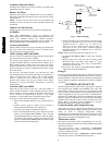
Verify gas pressures before turning on heat as follows:
1. Turn off field-supplied manual gas stop, located external to
unit.
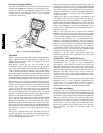
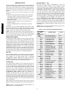
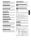
2. Connect pressure gauge to supply gas tap, located on
field-supplied manual shutoff valve. (See Fig. 6.)
3. Connect pressure gauge to manifold pressure tap.
4. Turn on field-supplied manual gas stop. Enter Service Test
mode by setting Service Test→TEST to “ON” using the
Scrolling Marquee display. Temporarily install the jumper
wire between “R” and “W1” on TB1. Use the Service Test
feature to set Service Test→HEAT→HT.1 to ON (first stage
of heat) using the Scrolling Marquee.
MANUAL SHUT OFF
(FIELD SUPPLIED)
PRESSURE TAP
(1/8˝ NPT PLUG)
GAS
SUPPLY
SEDIMENT TRAP
UNION
TO
UNIT
C09242
Fig. 6 − Field Gas Piping
5. After the unit has run for several minutes, verify the supply
gas pressure is between 5.5−in. wg to 13.0−in. wg, and the
manifold pressure is 3.50−in. wg on sizes 03−14,
3.00−in.wg on sizes 16−28 with a vertical supply or
2.95−in.wg on sizes 16−28 with a horizontal supply. If
manifold pressure must be adjusted, refer to Gas Valve
Adjustment section.
NOTE: Supply gas pressure must not exceed 13.0−in. wg.
6. Set Service Test→HEAT→HT.1 to OFF using Scrolling
Marquee.
7. Remove jumper wire if the unit will be operating under
thermostat mode. The jumper must remain if a space
temperature sensor (T-55, T-56, T-58, or System Pilot
device) will control the unit.
8. Exit Service Test mode by setting Service Test→TEST to
“OFF” using the Scrolling Marquee.
EnergyX
For units equipped with the EnergyX factory installed option, there
is an EnergyXv2 Supplement Installation Instructions in the unit’s
information packet. Follow the start up sequence and complete the
start up checklist contained in the EnergyXv2 manual to complete
unit startup.
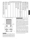
CONTROLS QUICK SET−UP
The following information will provide a quick guide to setting up
and configuring the 48/50PG and 48/50PM series units with
ComfortLink controls. Unit controls are pre-configured at the
factory for factory-installed options. Field-installed accessories will
require configuration at start-up. Service Test is recommended for
initial start−up. Additionally, specific job requirements may require
changes to default configuration values. See the CCN and Display
parameter tables and other sections of these instructions for more
details. Refer to the Major System Components or accessory
installation instructions for specific wiring detail.
Control Set Point and Configuration Log
During start up, accessory installation, and equipment service set
points and/or configuration changes might have to be made. When
setting set points or changing configuration settings,
documentation is recommended. The Control Log starting on page
192 should be filled out and left with the unit at all times, a copy
should also be provided to the equipment owner.
Thermostat Control
Wire accessory thermostat to the corresponding R, Y1, Y2, W1,
W2, and G terminals on the field connection terminal board located
at the unit control box.
The Unit Control Type configuration, Configuration
→UNIT→U.CTL, default value is for Thermostat (2) so there is
no need to configure this item.
The Thermostat Control Type, Configuration →UNIT→T.CTL,
selects the unit response to the thermostat inputs above.
48/50PG and PM