


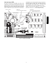
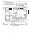
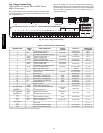
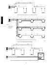
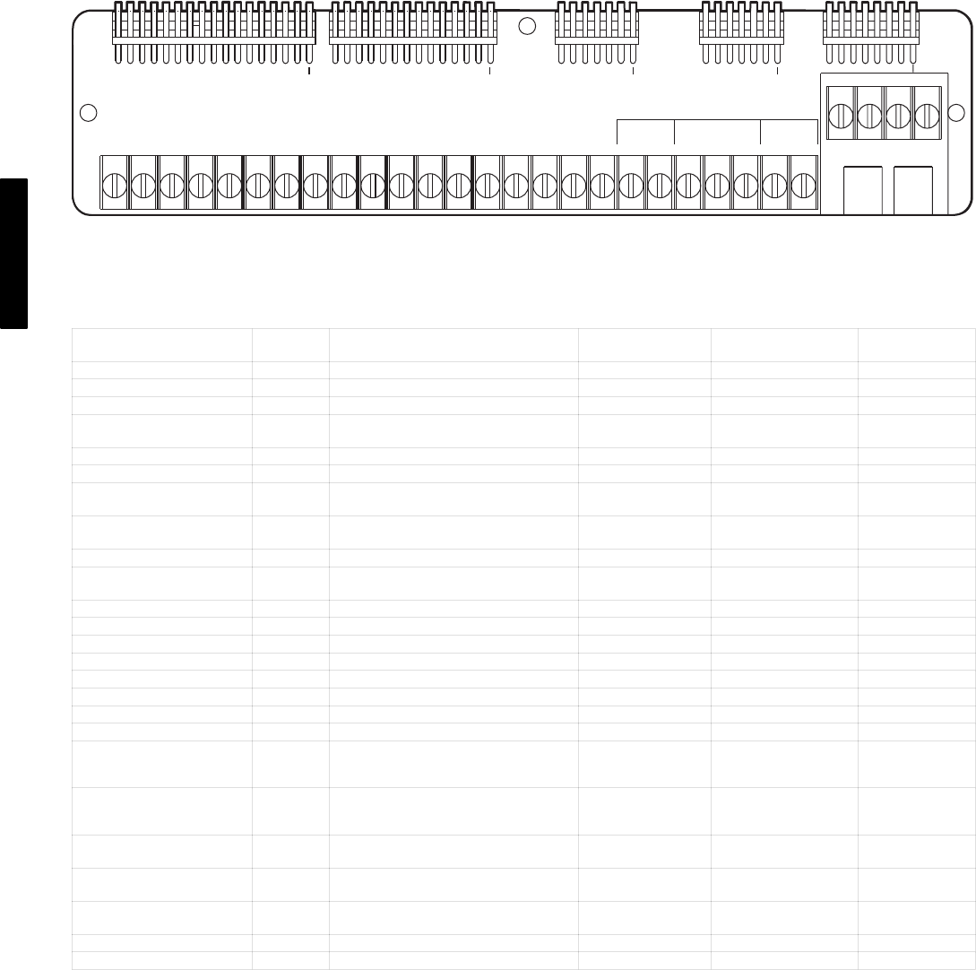
76
Low Voltage Terminal Strip
(TB1 on PG03−16 size and TB2 on PG20−28 and
PM16−28 size units)
This circuit board provides a connection point between the major
control boards and a majority of the field-installed accessories. (See
Fig. 43 and Table 26.)
The circuit breakers for the low voltage control transformers,
interface connection for the Carrier Comfort Network (CCN)
communication, and interface connection for the Local Equipment
Network (LEN) communications are also located on the low
voltage terminal strip.
SEPARATION OF CIRCUITS TO EACH 24V TRANSFORMER MUST BE MAINTAINED
1 2 3 4 5 6 7 8 9 10 R Y1 Y2
W1
W2 G C X 1 2 1 2 3 1 2
FAN STATUS
T55
J12
FIRE SHUTDOWN
RUN TEST
J13
7
8
J11
7
14
17
J10
LEN
CCN
CCN
(COM)
SHIELD
(-)
(+)
48HG500382
C07029
Fig. 43 − Low−Voltage Terminal Strip
Table 26 – Field Connection Terminal Strip
TERMINAL LABEL
DISPLAY
NAME
POINT DESCRIPTION
SENSOR
LOCATION
TYPE OF I/O
CONNECTION
PIN NUMBER
1 24 VDC Sensor Loop power 24 VDC output J10, 17
2 IAQ Indoor air quality sensor return/space 4-20 mA input J10, 16
3 Air quality & humidity sensor common Ground J10, 15
4
OAQ or
SP.RH
Outdoor air quality sensor or
Relative humidity sensor
field installed 4-20 mA input J10, 14
5 RM.OC Remote occupancy switch field installed 24 VAC input J10, 13
6 Switch power (ENTH, RM.OC, IAQ.S) 24 VAC output J10, 11-12
7
ENTH or
IAQ.S
Outdoor enthalpy switch, or
Indoor air quality switch
economizer, or
return/space
24 VAC input J10, 9-10
8* EC.CP
Economizer commanded position actu
ator (when in digital control)
economizer 2-10 VDC output J10, 6-8
9 Economizer signal common Ground J10, 3-5
10* EC.AP
Economizer position feedback (when in
analog control)
economizer
communication
2-10 VDC output
J10, 1-2
R 24 VAC power 24 VAC output J11, 11-14
Y1 Y1 Thermostat Y1 (1st stage cool) space 24 VAC input J11,10
Y2 Y2 Thermostat Y2 (2nd stage cool) space 24 VAC input J11, 9
W1 W1 Thermostat W1 (1st stage heat) space 24 VAC input J11, 7-8
W2 W2 Thermostat W2 (2nd stage heat) space 24 VAC input J11, 6
G G Thermostat G (Fan) space 24 VAC input J11, 5
C 24 VAC common 24 VAC output J11, 2-4
X ALRM Alarm output (normally open) 24 VAC output J11, 1
FIRE SHUTDOWN
or
HUMIDISTAT 1*
FDWN
or
HUM
Fire shutdown switch 24 VAC output
or
Humidistat switch input
supply/return/
space
switch input J12, 7
FIRE SHUTDOWN
or
HUMIDISTAT 2*
FDWN
or
HUM
Fire shutdown switch input
or
Humidistat switch 24 VAC output
supply/return/
space
switch input J12, 6
T55
1-2
SPT Space temperature (T55/56) space 10k thermistor J12, 4-5
T55
2-3
SPTO or
RAT
Space temperature offset (T56) or
Return air temperature
space or return 10k thermistor J12, 3-4
FAN STATUS
1-2
NOT USED J12, 1-2
LEN Local Equipment Network (LEN) communication J13, 6-8, 4-5
CCN Carrier Comfort Network (CCN) communication J13, 1-3, 4-5
* Refer to Third Party Control section for more information
48/50PG and PM