


52
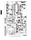
SCT.A
MOTORMASTER
SENSOR
SCT.A
MOTORMASTER
SENSOR
48/50PG03,04
(3rd return bend
down from top)
(bottom stub
of outside header)
48/50PG03-07
C09347
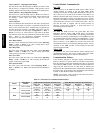
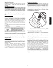
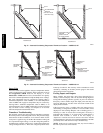
Fig. 23 − Saturated Condensing Temperature Thermistor Location — 48/50PG03−07
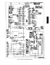
THERMISTOR
LOCATION
(SCT.B)
THERMISTOR
LOCATION
(SCT.B)
THERMISTOR
LOCATION
(SCT.A)
48/50PG08-12
THERMISTOR
LOCATION
(SCT.A)
48/50PG14
MOTORMASTER
SENSOR
(2nd stub from bottom
of outside header)
MOTORMASTER
SENSOR
(4th stub from bottom
of outside header)
C09348
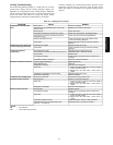
Fig. 24 − Saturated Condensing Temperature Thermistor Location — 48/50PG08−14
Sensor Trim
Corrective offsets can be applied to the space temperature and the
supply air temperature sensor readings. These corrections are set in
the Configuration→TRIM menu for the display, or in the
Maintenance→TRIM table for CCN. See the Indoor Air Quality
section for available adjustments to IAQ and OAQ sensor readings.
The space temperature may be corrected by entering either a
calibration temperature value in SPT.C, or an offset temperature
value in SPT.T. The supply-air temperature may be corrected by
entering either a calibration temperature value in SAT.C, or an
offset temperature value in SAT.T. Temperature corrections should
only be made if sensor readings are compared to an accurate
reference temperature measurement device.
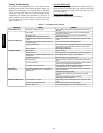
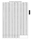
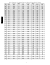
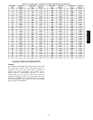
Transducer Troubleshooting
The electronic control uses suction pressure transducers to measure
the suction pressure of the refrigerant circuits. The pressure/voltage
characteristics of these transducers are in shown in Table 22, the
5vdc power is applied to legs A and B of the transducer and legs B
to C represent the signal voltage. To use the voltage drop table for
troubleshooting, read the voltage across A and B, then subtract the
voltage reading from B to C. This is the voltage drop which can be
looked up in table 22. The accuracy of these transducers can be
verified by connecting an accurate pressure gauge to the second
refrigerant port in the suction line.
Forcing Inputs and Outputs
Many variables may have their value forced through CCN or
directly at the local display. This can be useful during diagnostic
testing and also during operation, typically as part of an advanced
third party control scheme. Input and output points that may be
forced are indicated as ‘forcible’ in the write status column of the
display and CCN tables.
If the user needs to force a variable, follow the same process as
when editing a configuration parameter. A forced variable will be
displayed on the Scrolling Marquee with a blinking period “.”
following its value. A forced value on Navigator accessory is
indicated with a blinking “f”. A forced value on CCN devices is
indicated with “Control” if forced at the unit display, or
“Supervisor” if forced via CCN. To remove a local force with the
Scrolling Marquee, select the point with the ENTER key and then
press the up-arrow and down-arrow keys simultaneously.
NOTE: In the case of a control power reset, any force in effect at
the time of power reset will be cleared.
48/50PG and PM