


6
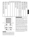
Conventions Used in This Manual
The following conventions for discussing configuration points for
the local display (Scrolling Marquee or Navigator accessory) will
be used in this manual.
Point names will be written with the Mode name first, then any
submodes, then the point name, each separated by an arrow symbol
(→). Names will also be shown in bold and italics. As an example,
the Thermostat Control Type which is located in the Configuration
mode, and Unit sub-mode would be written as Configuration→
UNIT→T.CTL.
This path name will show the user how to navigate through the
local display to reach the desired configuration. The user would
scroll through the modes and sub-modes using the up and down
keys. The arrow symbol in the path name represents pressing
ENTER to move into the next level of the menu structure.
When a value is included as part of the path name, it will be shown
at the end of the path name after an equals sign. If the value
represents a configuration setting, an explanation will be shown in
parenthesis after the value. As an example,
Configuration→UNIT→T.CTL = 1 (1 Stage Y1).
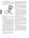
Pressing the ESCAPE and ENTER keys simultaneously will scroll
an expanded text description of the point name across the display.
The expanded description is shown in the local display tables but
will not be shown with the path names in text.
The CCN point names are also referenced in the local display
tables for users configuring the unit with CCN software instead of
the local display. See Appendix A of this manual.
START-UP
IMPORTANT: Do not attempt to start unit, even momentarily,
until all items on the Start−Up Checklist (last page) and the
following steps have been read/completed.
Unit Preparation
Check that unit has been installed in accordance with these
installation instructions and all applicable codes.
Compressor Mounting
Compressors are internally spring mounted. Do not loosen or
remove compressor holddown bolts.
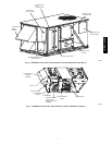
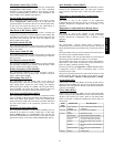
Refrigerant Service Ports
Each independent refrigerant system has a total of 3 Schrader-type
service gauge ports per circuit. One port is located on the suction
line, one on the compressor discharge line, and one on the liquid
line. Be sure that caps on the ports are tight.
Crankcase Heater(s)
Compressor crankcase heater operation varies depending on the
unit size and type. In general for all units, the crankcase heaters are
energized if there is power to the unit, the compressor is not
operating, and the ambient temperature is below 75F.
IMPORTANT: Unit power must be on for 24 hours prior to
start−up. Otherwise, damage to compressor may result.
Compressor Rotation
UNIT DAMAGE HAZARD
Failure to follow this caution may result in unit damage.
Improper wiring will cause compressor stoppage and alarm.
Correct wiring by switching leads as indicated below.
CAUTION
!
On 3-phase units, it is important to be certain the compressors are
rotating in the proper direction. To determine whether or not
compressors are rotating in the proper direction, use a
phase-rotation meter on the unit input power to check for
L1-L2-L3 or clockwise rotation or use the Service Test mode to
energize a compressor. If the compressor is rotating in the wrong
direction, the controls will stop the compressor and display alarm
for “Circuit x Failure to Pressurize,” where x is the corresponding
A, B or C compressor circuit.
NOTE: Indoor or outdoor fan rotation direction may not indicate
proper input power phase sequence, as some 3-phase units use
single-phase fan motors.
To correct the wrong compressor rotation direction, perform the
following procedure:
1. Turn off power to the unit and lock out the power.
2. Switch any two of the incoming unit power leads.
3. Turn on power to the unit.
4. Verify corrected compressor rotation.
Power Supply
All 208/230-v units are factory wired for 230-v power supply. If
the 208/230-v unit is to be connected to a 208-v power supply, the
transformers (TRAN1, TRAN2 and TRAN3) must be rewired by
moving the wire from the 230-volt connection and moving to the
200-volt terminal on the primary side of the transformer. Refer to
unit label diagram for additional information.
Internal Wiring
Check all electrical connections in unit control boxes; tighten as
required.
Evaporator Fan
Fan belt and variable pulleys are factory−installed, but may need to
be adjusted for specific applications. Be sure that the fans rotate in
the proper direction. See Appendix C for unit specific fan
performance data. See Appendix D for unit specific air quality
limits, evaporator fan motor specifications, FIOP static pressures,
and fan RPM for various motor pulley settings. To alter fan
performance, see Evaporator Fan Performance Adjustment in the
Service section.
NOTE: Units equipped with Adaptive Fan still must conform to
minimum CFM requirements at all times and the fan speed
configurations must be set for this compliance.
48/50PG and PM