


S-7200C
CONTENTS
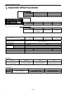
1. MACHINE SPECIFICATIONS.............. 1
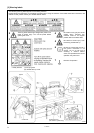
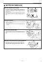
2. NOTES ON HANDLING........................
2
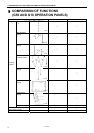
3. COMPARISON OF FUNCTIONS
(G50 AND G10 OPERATION PANELS)...
3
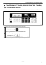
4. FUNCTION SETTINGS
(G50 OPERATION PANEL) ..................
4
4-1.
List of advanced functions ................................... 4
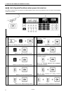
4-2.
List of special functions when power is turned on.. 5
4-3.
Maximum sewing speed and start backtack
sewing speed setting methods............................. 6
4-4.
Using the LOCK key ............................................ 7
4-5.
Memory switch setting method (Standard)........... 8
4-6.
Memory switch setting method (Advanced) .........13
4-7.
Data initialization function .................................... 22
4-8.
Error history checking method ............................. 23
4-9.
Input checking method.........................................24
4-10.
Output checking method.................................... 29
4-11.
Protection settings .............................................32
4-12.
Software version checking method....................35
4-13.
Viewing maintenance information ......................36
4-14.
Adjusting the sewing machine reference
position ..............................................................37
5. FUNCTION SETTINGS
(G10 OPERATION PANEL) ................. 38
5-1.
List of special functions when power is turned on.. 38
5-2.
Function setting method.......................................39
5-3.
Data initialization function .................................... 41
5-4.
Error history checking method ............................. 42
5-5.
Input checking method.........................................43
5-6.
Output checking method ......................................48
5-7.
Protection settings ...............................................51
5-8.
Software version checking method ......................54
5-9.
Viewing maintenance information ........................ 55
5-10.
Adjusting the sewing machine reference position.. 56
6. SETTING THE DIP SWITCHES
(G50 AND G10 OPERATION PANELS)... 57
7. MECHANICAL DESCRIPTIONS .........
58
7-1.
Upper shaft and needle bar mechanism .............. 58
7-2.
Lower shaft and rotary hook mechanism ............. 59
7-3.
Feed mechanism ................................................. 60
7-4.
Quick reverse mechanism
(quick back mechanism) ......................................61
7-5.
Lubrication mechanism
(thread take-up and rotary hook).......................... 62
7-6.
Thread trimming mechanism................................ 63
7-6-1. Thread trimming mechanism operation
sequence.................................................... 63
7-6-2. Upper and lower thread trimming sequence ...65
7-7.
Tension release mechanism................................ 66
7-8.
Thread wiper mechanism (option device)............ 67
8. DISASSEMBLY ....................................68
8-1.
Knee lifter assembly ............................................ 68
8-2.
Cable tie .............................................................. 69
8-3.
Connector............................................................ 69
8-4.
Operation panel and head detector unit .............. 70
8-5.
Covers and bobbin winder unit ............................ 71
8-6.
Tension release wire and thread trimmer solenoid.. 72
8-7.
Wick holder and oil tube (-[]0[] specifications) ..... 73
8-8.
Oil tank, bed bottom cover and sub tank ............. 74
8-9.
Stand ................................................................... 75
8-10.
Safety switch and quick reverse solenoid.......... 75
8-11.
Needle, presser foot and R-actuator ................. 76
8-12.
Thread tension mechanism ............................... 76
8-13.
Needle plate, feed dog, etc................................ 77
8-14.
Bobbin case, rotary hook and thread trimmer
mechanism........................................................ 78
8-15.
Feed bar mechanism......................................... 79
8-16.
Feed rock shaft.................................................. 79
8-17.
Presser foot mechanism.................................... 80
8-18.
Knee lifter lever mechanism .............................. 81
8-19.
Tension pulley ................................................... 81
8-20.
Needle bar and thread take-up mechanism....... 82
8-21.
Pulley and motor ............................................... 83
8-22.
Timing belt......................................................... 84
8-23.
Feed mechanism (1) ......................................... 84
8-24.
Feed mechanism (2) ......................................... 85
8-25.
Feed mechanism (3) ......................................... 86
8-26.
Lower shaft, lower shaft gear
and feed regulator unit ...................................... 87
8-27.
Plunger, rotary hook shaft, rotary hook shaft
gear and thread trimmer cam ............................ 88
8-28.
Reverse lever .................................................... 88
9. ASSEMBLY ..........................................89
9-1.
Stitch length dial and feed regulator mechanism... 90
9-2.
Reverse lever ...................................................... 91
9-3.
Plunger, rotary hook shaft, rotary hook shaft gear
and thread trimmer cam....................................... 92
9-4.
Lower shaft, lower shaft gear and
feed regulator unit................................................ 93
9-5.
Feed mechanism (1)............................................ 94
9-6.
Feed mechanism (2)............................................ 95
9-7.
Upper shaft mechanism....................................... 96
9-8.
Timing belt........................................................... 97
9-9.
Pulley, motor and ground wire............................. 97