


S-7200C
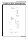
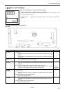
17. CONNECTOR LAYOUT DIAGRAM (MAIN PCB)
151
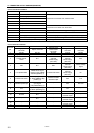
<List of connector numbers>
Connector No. Name Description
P8 Head detector unit connector
P12 Solenoid-type pressure lifter connector
P13 Sewing machine connector
P6 Resolver connector
P7 Operation panel connector
Connects to connector from machine head.
P3 Relay connector
P4 Coupler connector
Connects to connector from drive PCB.
P1 DC power connector Supplies power from switching power supply PCB.
P14 Treadle connector Connects to connector from treadle unit.
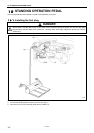
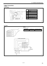
P5 Standing operation connector Connects to plug for standing operation (sold separately).
P11 SD connector (for writing) Connects to special writing unit.
P9 Option connector (not mounted) Output signals for external devices are available.
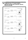
<List of terminal numbers>
P5 P9 P12 P13 P1
Terminal
No.
Standing operation
connector
Option connector
Solenoid-type
pressure lifter
connector
Sewing machine
connector
DC power
connector
1 DC+8V DC+5V Ground Ground DC+8V
2 High-speed switch N.C N.C N.C DC+5V
3
Thread trimmer
switch
N.C
Presser foot lifter
solenoid
Power supply
(DC+30V)
Thread trimming
solenoid
Power supply
(DC+30V)
S0V
4 S0V N.C S0V
Thread wiper
solenoid
Power supply
(DC+30V)
DC line voltage
signal
5 Low-speed switch
Needle down signal
output (L level: Needle
down stop position) (*1)
Presser foot switch
Quick reverse
solenoid
Power supply
(DC+30V)
0V
6 Presser foot switch
Needle up signal output
(L level: Needle up stop
position) (*1)
Presser foot lifter
solenoid output
S0V N.C
7 Variable speed input
Machine shaft
sync signal
(128 pulses/stitch) (*1)
- S0V DC+30V
8 N.C
Operation signal output
(H level: Operating) (*1)
- N.C -
9 N.C N.C - N.C -
10 Ground N.C -
Thread trimming
solenoid output
-
11 - N.C -
Thread wiper
solenoid output
-
12 - - -
Quick reverse
solenoid output
-
13 - - - Actuator switch -
14 - - - Safety switch -
(*1) This is open collector output.