


S-7200C
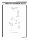
14. CONTROL BOX AND MOTO
R
146
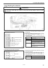
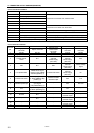
14-2. Checking the solenoids
DANGER
Wait at least 5 minutes after turning off the power switch and disconnecting the power cord from the wall outlet
before opening the face plate of the control box. Touching areas where high voltages are present can result in
severe injury.
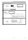
<Machine head>
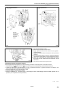
1. Disconnect the 14P sewing machine connector (1) from
the main PCB.
2. Measure the resistance of the sewing machine connector
14P (1) using an ohmmeter in the x 1 range.
If the values are as shown in the table below, the
connector is normal.
Between 3–10 Thread trimmer solenoid:
Approx. 7.6 Ω
Between 4–11 Thread wiper solenoid: Approx. 10.1Ω
Between 5–12 Quick reverse solenoid: Approx. 4.5Ω
When actuator is pressed: 0Ω Between 6–13
When actuator is released:
∞
Ω
When machine head is upright (switch
ON): 0 Ω
Between 7–14
When machine head is tilted back
(switch OFF):
∞
Ω
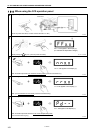
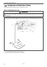
<Solenoid-type presser lifter connector>
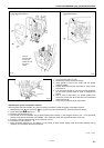
1. Disconnect the 6P solenoid-type presser lifter connector
(2) from the main PCB.
2. Measure the resistance of the solenoid-type presser lifter
connector 6P (2) using an ohmmeter in the x 1 range.
If the values are as shown in the table below, the
connector is normal.
Between 3–6 Presser lifter solenoid: Approx. 9.6 Ω
When knee switch is pressed: 0 Ω Between 4–5
When knee switch is released:
∞
Ω
2118B
Sewing machine connector 14P
1886M
Thread trimmer solenoid
Thread wiper solenoid
Quick reverse solenoid
A
ctuator switch
Safety switch
Solenoid-type presser lifter connector 6P
2331M
Knee switch
Presser lifter solenoid