


S-7200C
10. ADJUSTMENTS
124
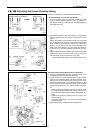
10-13. Adjusting the thread trimming timing
Remove the presser foot, needle plate and feed dog.
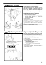
< Thread trimming cam position adjustment >
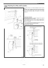
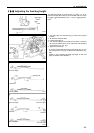
1. Turn the machine pulley to raise the needle bar 5 mm
from its lowest position (reference line (a) position) so
that reference line (b) is aligned with the bottom edge of
the needle bar bush.
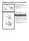
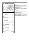
2. At the above position, push the plunger (1) of the thread
trimming solenoid with your finger in the direction of the
arrow.
Adjust the position of the thread trimmer cam (2) at this
time so that the roller shaft (4) of the thread trimmer cam
lever assembly (3) touches the hollow (c) of the thread
trimmer cam (2) and so that the clearance between the
edge of the thread trimmer cam (2) and the roller shaft (4)
is 0.6 to 0.8 mm, and then tighten the set screws (5). (Fig.
[A])
3. Check that the clearance between the edge of the thread
trimmer cam (2) and the roller shaft (4) is 0.5 mm when
the roller shaft (4) returns to the right. (Fig. [B])
* Tighten the two set screws (5) to approximately 4 N.m.
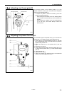
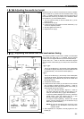
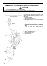
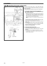
<Movable knife and fixed knife position adjustment >
1. Turn the machine pulley, and then push the plunger (1) of
the thread trimming solenoid with your finger.
2. In this condition, turn the machine pulley until the roller
shaft (4) of the thread trimmer cam lever assembly (3) is
sitting on top of the thread trimmer cam (2), then move
the thread trimmer lever (7) to adjust its position so that
the tip of the fixed knife (5) and the blade of the movable
knife (6) are meshed by 1 mm, and then tighten the screw
(8).
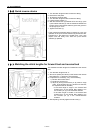
* Adjust so that the meshing amount is 1 mm at this time,
by using the position where the mating marks on the
thread trimmer holder and the bushing are aligned as a
guide.
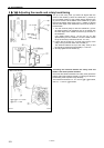
* Tighten the screw (8) so that there is no play in the
forked shaft (9).
* The lower thread finger (10) must be underneath the
movable knife (6).
3. Install the feed dog, needle plate and presser foot.
Lowest position of needle bar
Reference
line (b)
Reference
line (a)
Raised 5 mm
Direction of
cam rotation
Mating mark
1204B
4351M
4352M
1207B
4353M