


S-7200C
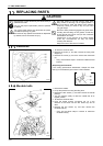
11. REPLACING PARTS
134
< Timing belt installation check >
1. Check that the needle and rotary hook timing is correct.
(Refer to “10-12. Adjusting the needle and rotary hook
timing”.)
* If they are correct, continue from step 5, otherwise
continue from step 2.
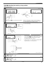
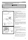
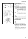
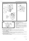
2. Check that the needle and feed mechanism timing is
correct.
Turn the machine pulley (5) forward to lower the feed dog
(16) from its highest position until it is aligned with the top
of the needle plate (17), and check that the tip of the
needle is at the following position at this time.
The top of the feed dog (16) and the top of
the needle plate (17) should be aligned, and
the point of the needle should be
approximately 1 mm below the needle plate
(17).
The top of the feed dog (16) and the top of
the needle plate (17) should be aligned, and
there should be a clearance of approximately
3 mm between the point of the needle and
the needle plate (17).
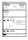
* If it is not in the correct position, carry out the following
steps.
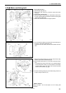
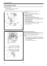
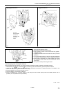
1) Tilt back the machine head, and then loosen the two set
screws (19).
2) Turn timing pulley D (6) forward to lower the feed dog
(16) until it is at the same height as the needle plate (17).
3) While holding the vertical cam (20) with one hand so that
it will not move, turn the machine pulley (5) forward to
lower the needle to the correct position.
4) Tighten the two set screws (19).
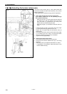
3. Adjust the needle and rotary hook timing so that it is
correct.
(Refer to “10-12. Adjusting the needle and rotary hook
timing”.)
4. Check that the thread trimming timing is correct. If it is not
correct, adjust it by following the adjustment procedure.
(Refer to “10-13. Adjusting the thread trimming timing”.)
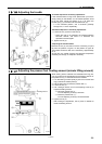
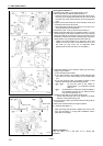
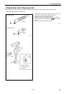
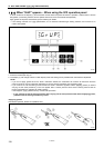
5. Set the sewing machine to needle up stopping, and then
operate the sewing machine and let it stop. Check that the
reference line (d) on the machine pulley (5) is within the
range of the mark (e) on the motor cover (3) at this time.
(Refer to previous page)
If the reference line (d) is not aligned within the mark (e),
loosen the three screws (9), adjust the position of the
machine pulley (5) so that the reference line (d) is aligned
within the mark (e), and then tighten the three screws (9).
6. If adjustment of the needle up stop position is necessary,
adjust according to the procedure in “10-15. Adjusting the
needle up stop position”.
<-[][]S・[][]3> <-[][]5>
Approx. 1mm
Approx. 3mm
4362M
4363M
4360M
<-[][]S・[][]3>
<-[][]5>