3 - 12
3.2.6 Creating a program
3 CREATING PROGRAM IN STRUCTURED LADDER/FBD LANGUAGE
GX Works2
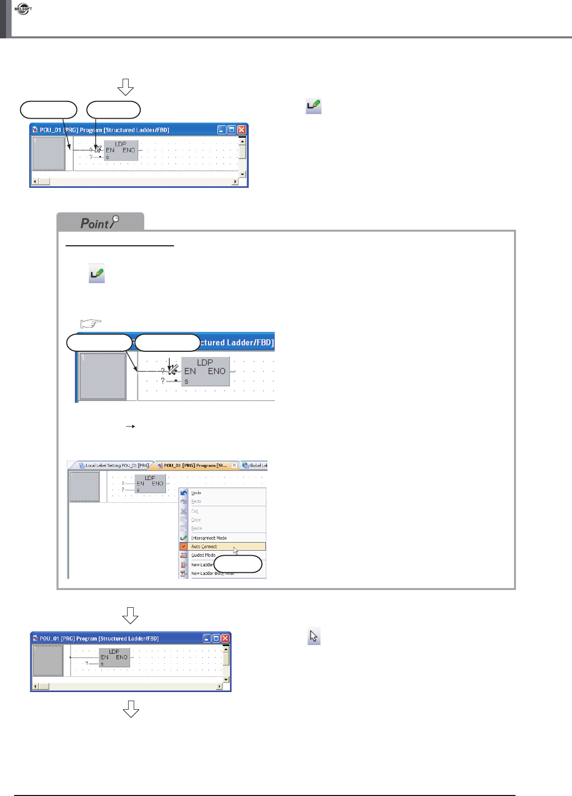
3. Click (Interconnect Mode) on the Structured
Ladder/FBD toolbar to specify the Interconnect
mode.
Click the start point and end point in this order to
draw a grid line as shown left.
(GX Works2 is using the Auto Connect function
described in "Point".)
Connection with grid line
Connect ladder symbols such as contacts, coils, Function and Function block with grid lines.
Click (Interconnect Mode), and draw a grid line.
Turn ON the Auto Connect function in the interconnect mode to easily draw a grid line only by specifying the
start point and end point using the mouse.
Refer to the following manual for the details:
GX Works2 Version 1 Operating Manual (Structured Project)
Perform either of the following procedures to turn ON the Auto Connect function.
● Select [Edit] [Auto Connect] to put a check mark.
● Right-click the Structured Ladder/FBD work window to display the menu, and select "Auto Connect" to put a check
mark.
4. Click (Select Mode) on the Structured
Ladder/FBD toolbar to specify the Select mode.
Start Point End Point
Start Point End Point
Click it.
(To the next page)


