


Pulse Modulation
Pulse Modulation
Pulse modulation can be accepted from an external source at the
PULSE connector or can be internally generated. The damage levels
of the PULSE input are
+lO
and -5 V DC. The input impedance is
50R. A function generator must be capable of driving TTL levels
into a
5Ofl
load. With no input signal, the pulse input is held low, so
activating pulse with no input causes RF output to shut off.
The synthesizer can also produce a 27.778 kHz square wave for use in
HP scalar network analyzers. Synthesizers with Option 002 internally
generate a synthesized pulse. The synthesizer provides internal
pulse modulation with pulse widths adjustable with 1 ps resolution
(adjustable with 25 ns resolution with Option 002).
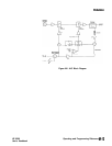
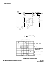
Leveling
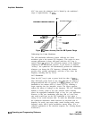
Pulse leveling performance depends on the accuracy of the diode
detector which measures the RF amplitude. The ALC block
diagram, Figure M-4, shows the pulse modulation input signal to
the synthesizer which controls a pulse modulator. The pulse input
is represented by trace 1 in Figure
M-5.
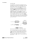
The pulse modulator is
either full on or full off. The amplitude, when the pulsed RF is on,
is controlled by the linear modulator used for CW leveling and AM.
Trace 2 is the resultant RF pulse, which is the RF output. This pulse
is detected by the diode detector. It trails the pulse input because of
propagation delays in the pulse modulator and its drive circuits.
The output of the detector is amplified by a logarithmic amplifier
(log amp). Trace 3 is the output of the log amp. Note that this
signal is delayed from the RF output signal and that the rise time
is slower. This is a result of the bandwidth of the detector and the
log amp. The amplitude of trace 3 is summed with the reference
signal from the level DAC and the difference (error) signal drives
an integrate-and-hold circuit.
The integrator output drives the RF
output power level via the linear modulator. When the sum of the
detected and reference signals is 0 volts, the output of the integrator
is held at a constant level and the RF output is leveled.
Trace 4 is the delayed signal from the pulse input which controls the
switch in the integrate-and-hold circuit. Trace 4 is timed to coincide
with trace 3. Since the integrate-and-hold switch is closed only when
trace 3 is high, the integrator responds to correct the power level
only when the RF power is on.
HP 8360
User’s Handbook
Operating and Programming Reference
M-19