


Fitness
Menu
Theory of operation
The unparalleled leveled output power accuracy and flatness of the
HP 8360 series synthesizer. This is achieved by using a new digital
(versus analog) design to control the internal automatic leveling
circuitry (ALC).
An internal detector samples the output power to provide a dc
feedback voltage. This voltage is compared to a reference voltage
which is proportional to the power level chosen by the user. When
there is a discrepancy between voltages, the power is increased
or decreased until the desired output level is achieved. For
comprehensive theory on the ALC system, refer to the
[ALC)
entry in
the “A” section of this manual.
The factory-generated internal calibration data of the synthesizer
is digitally segmented into 1601 data points across the start/stop
frequency span chosen. Subsequently, these points are converted into
1601 reference voltages for the ALC system. The digital ALC control
scheme not only delivers excellent power accuracy and flatness at
the output port of the synthesizer, but also provides the means to
execute the user flatness correction feature.
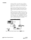
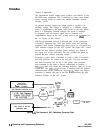
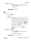
Generally, a power meter is required to create a table of correction
data that produces flat power at the test port. You may measure
and enter correction data for up to 801 points. The correction
data contained in the table is linearly interpolated to produce a
1601-point data array across the start/stop frequency span set on the
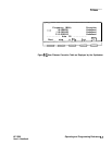
synthesizer. The 1601-point data array is summed with the internal
calibration data of the synthesizer (Figure
F-3).
When user flatness
correction is enabled, the sum of the two arrays produces the 1601
reference voltages for the ALC system.
1601 Equodistont
Point Array
Accessible Only
From
a
Computer
User Flatness Correction Array
CorPoir
1601 Points
far ALC
1601 Points of Internal
Calibration Data
Figure F-3. The Sources of ALC Calibration Correction Data
F-6
Operating and Programming Reference
HP 8360
User’s Handbook