


Amplitude
Modulation
Amplitude modulation can be accepted from an external source at
the AM connector or can be internally generated by synthesizers with
Option 002. The damage level of the AM input is
f15
V DC. The
input impedance of the AM connector is
500.
A jumper on the
A10
ALC board allows you to change the input impedance to 2 kR (See
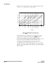
“Adjustments” in the Service Guide.) The AM can be scaled either
linearly at 100% per volt or exponentially at 10 dB per volt.
When internal AM is chosen (Option 002), the rate and depth are set
by softkeys in the AM menu. The waveform menu provides a choice
of sine, square, triangle, ramp, or noise waveforms. The monitor
menu lets you output the internally generated modulation waveforms
to the rear panel AM/FM OUTPUT connector. The AM output is
scaled the same as it is generated, either
100%/V
or 10
dB/V.
This
connector can drive
5OQ
or greater. The monitor menu also lets you
display the value of the AM depth.
UNLVLED Message
The maximum leveled output is limited by the synthesizer’s
maximum leveled output power specification. (Individual synthesizers
may be capable of greater leveled output power; the unleveled
message indicates the actual limit.) Amplitude modulation adds to
and subtracts from the reference RF power level. If an
IJNLVLED
message appears on the display, you may be trying to modulate
beyond the synthesizer’s maximum output power capability.
OVRMOD Message
The maximum AM depth is limited to approximately 90% by the
detector’s ability to sense low power levels. If you try to amplitude
modulate too deep without using deep AM mode (explained later),
you will see an
l&??t$:~D
message displayed on the message line. Also,
if you modulate below -20
dBm
ALC level without using deep AM
mode or below -50
dBm
with deep AM or search ALC mode, you
will see an
OVRt4OD
message.
Dynamic Range
The ALC and attenuator combination (when an optional attenuator
is present) are automatically set by the synthesizer to keep the ALC
in its most accurate range (0 to -10
dBm).
This is called the coupled
attenzlator
operating mode.
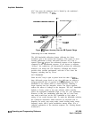
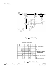
For applications where modulating across an attenuation switch point
is undesirable, you can uncouple the attenuator and manually set the
power level of the ALC and the attenuator.
For example, setting the power level to 0
dBm
in coupled mode will
give an ALC level of 0
dBm
and 0 dB of attenuation. In uncoupled
mode, the attenuator can be set to 10 dB and the ALC to
+lO
dBm,
giving 0
dBm
output power and greater AM depth potential. The
ALC can now be varied over its entire range and the attenuator
remains at a fixed level.
M-14 Operating and Programming Reference
HP 8360
User’s Handbook