


ModOut
On/Off FM
Function Group
Menu Map
Description
Programming Codes
See Also
(MOD)
4
This
softkey
(Option 002 only) lets you output the
internally-
generated frequency modulation waveforms to the rear panel AM/FM
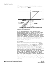
OUTPUT connector. When scaled exponentially at 10
dB/V,
the
maximum output voltage is offset to 0 V and the minimum voltage
level is -4 V.
SCPI:
MODulation:OUTput:SOURce FM
MODulation:OUTput:STATe
ONlOFFlllO
Analyzer: NONE
m,
also see “FM” and “Modulation”.
Modulation
General Circuit Theory
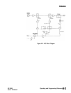
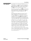
The synthesizer’s amplitude and pulse modulation performance is
directly tied to the ALC (Automatic Level Control) system. Refer to
the ALC block diagram in Figure M-l. The ALC system controls the
amplitude or power level of the RF output. A portion of the output
signal is detected, summed with the reference level signal, and the
difference (error) signal drives an integrate-and-hold circuit. The
integrator output drives the RF output power level via the linear
modulator. When the sum of the detected and reference signals is
0 volts, the output of the integrator is held at a constant level and
the RF output is leveled. This loop is bandwidth-limited by the
integrator and the integrate-and-hold circuit. Notice, however, that
there is a feedforward path that allows changes in power level that
are bandwidth-independent from the rest of the ALC loop. Power
level information supplied by the level DAC and AM input travels
the feedforward path to drive a linear modulator. (See
(ALC)
for
additional information on the ALC system.)
M-12 Operating and Programming Reference
HP 8360
User’s Handbook