


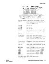
CONNECTORS
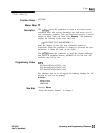
MOO Cl
+5v
RMRVED
MOO ANLG GND
MOD
D2
\ \
MOD CO
+RV
+15V
/
RESERVED/fUUP
CNTL
MOD
\
MODSENSE
MOO
bl
DIG
;rD
MT
L’i
(COAX)
-i5v
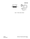
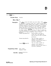
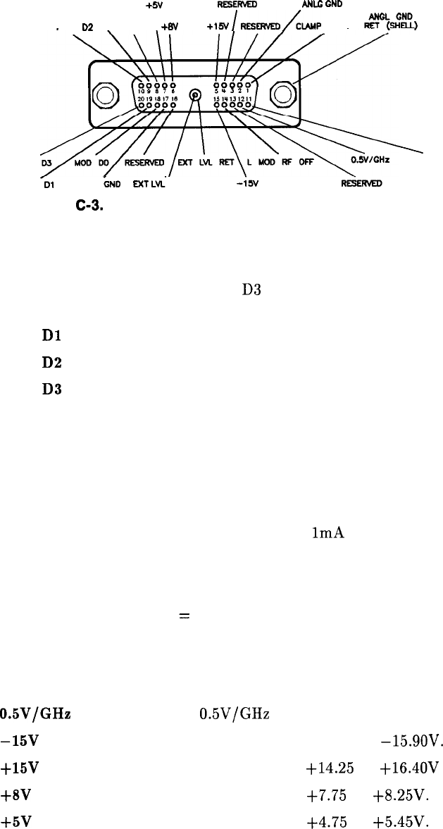
Figure
C-3.
Interface Signals of the Source Module Connector
The codes indicated on the illustration above translate as follows:
MOD DO
MOD
Dl
MOD
D2
MOD
D3
MOD CO
MOD Cl
CLAMP CNTL
MOD SENSE
L MOD RF OFF
EXT LVL RET
EXT LVL
0.5V/GHz
-15v
+15v
+8V
+5v
DIG GND
MOD ANLG GND
ANLG GND RET
Source module data line zero. Signals MOD DO
through MOD
D3
are the mm source module
data bus lines (bi-directional).
Data line one.
Data line two.
Data line three.
Source module control line zero. Signals MOD
CO and MOD Cl are the control lines for the
read/write to and from the mm source module.
Control line one.
Source module clamp control (not used).
Source module sense. A
1mA current is injected
on this line by the mm source module to
indicate its presence. This signal always equals
ov.
Low
=
RF off. Source module RF is turned off.
Source module external leveling return.
Source module external leveling input, from the
mm source module.
Internal
0.5V/GHz
to the mm source module.
Power supply. Range is -14.25 to
-15.9OV.
Power supply. Range is
+14.25
to +16.4OV
Power supply. Range is
i-7.75
to
+8.25V.
Power supply. Range is
t4.75
to
t5.45V.
Digital ground.
Source module analog ground.
Analog ground return.
HP 8360
User’s Handbook
Operating and Programming Reference
C-l 1