


6-22 Operation MN1928
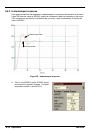
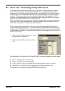
6.8 Servo axis - tuning for velocity control
Drives designed for velocity control incorporate their own velocity feedback term to provide
system damping. For this reason, KDERIV (and KVEL ) can often be set to zero.
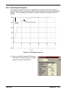
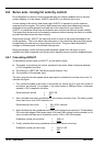
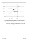
Correct setting of th e velocity feed forward gain KVELFF is important to get the optimum
response from the system. The velocity feed forward term takes the instantaneous velocity
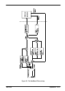
demand from the profile generator and adds this to the output block (see Figure 28).
KVELFF is outside the closed loop an d therefore does not have an ef fect on system stability.
This means that the term can be increased to maximum without causing the motor to oscillate,
provided that other terms are setup correctly.
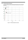
When setup correctly, KVELFF will cause the motor to move at the speed demanded by the
profile generator. This is true without the other terms in the closed loop doing anything except
compensating for small errors in the position of the motor . This gives faster response to
changes in demand speed, with reduced following error .
Before proceeding, confirm that the encoder feedback signals from the motor or servo
amplifier have been connected, and that a positive demand causes a positive feedback signal.
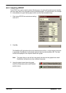
6.8.1 Calculating KVELFF
To calculate the correct value for KVELFF, you will need to know:
H The speed, in revolutions per minute, produced by the motor when a maximum demand
(+10V) is applied to the drive.
H The setting for LOOPTIME. The factory preset setting is 1ms.
H The resolution of the encoder input.
The servo loop formula uses speed values expressed in quadrature counts per servo loop.To
calculate this figure:
1. First, divide the speed of the motor, in revolutions per minut e, by 60 to give the number of
revolutions per second. For example, if the motor speed is 3000rpm when a maximum
demand (+10V) is applied to the drive:
Revolutions per second = 3000 / 60
=
50
2. Next, calculate how many r evolutions will occur during one servo loop. The factory pr eset
servo loop time is 1ms (0.001 seconds), so:
Revolutions per servo loop = 50 x 0.001 seconds
=
0.05
3. Now calculate how many quadrature encoder counts there are per revolution. The NextMove
ES counts both edges of both pulse trains (CHA and CHB) coming from the encoder , so for
every encoder line there are 4 ‘quadrature counts’. With a 1000 line encoder:
Quadrature counts per revolution = 1000 x 4
=
4000
4. Finally , calculate how many quadrature counts there are per servo loop:
Quadrature counts per servo loop = 4000 x 0.05
=
200