


5-20 Input / Output MN1928
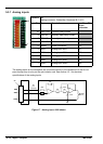
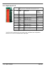
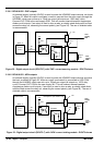
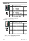
5.3.6.1 BPL010-502 - PNP outputs
An external supply (typically 24VDC) is used to power the UDN2982 output devices, as shown
in Figure 22. When an output is activated, current is sourced from the user supply through the
UDN2982, which can source up to 75mA per output (all outputs on, 100% duty cycle).
Connect OUT COM to the user supply GND. This will connect internal transient suppression
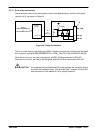
diodes on all outputs. If an output is used to drive a relay, a suitably rated diode must be fitted
across the relay coil, observing the correct polarity (see Figure 24). The use of shielded cable
is recommended.
OUTX.0
DOUT0
OUT COM
6
96
pin
connector
1
9
‘X6’
NextMove ES
Control
circuitry
+5V
‘X11’
2k2
UDN2982
TLP521-4
Back plane & opto-isolator card
User
supply
24V
User
supply
GND
Output
Load
USR V+
USR COM
10
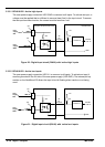
Figure 22 - Digit a l output circuit (DOUT0-7) with ‘PNP’ current sourcing module - DOUT0 shown
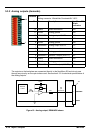
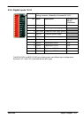
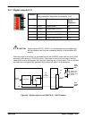
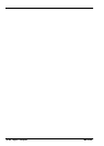
5.3.6.2 BPL010-503 - NPN outputs
An external supply (typically 24VDC) is used to power the UDN2803 output devices and drive
the load, as shown in Figure 23. When an output is activated it is connected to USR COM
through the ULN2803, which can sink up to 150mA per output (all outputs on, 100% duty
cycle). Connect OUT COM to the user supply 24V. This will connect internal transient
suppression diodes on all outputs. If an output is used to drive a relay , a suitably rated diode
must be fitted across the relay coil, observing the correct polarity (see Figure 24). The use of
shielded cable is recommended.
OUTX.0
USR V+
DOUT0
USR COM
6
96
pin
connector
1
10
‘X6’
NextMove ES
Control
circuitry
+5V
‘X11’
2k2
ULN2803
TLP521-4
Back plane & opto-isolator card
User
supply
24V
User
supply
GND
Output
Load
OUT COM
9
Figure 23 - Digit al output circuit (DOUT0-7) with ‘NPN’ current sinking module - DOUT0 shown