


6-8 Operation MN1928
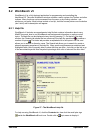
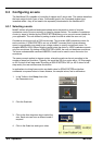
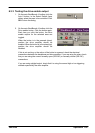
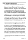
4. If you are going to use
the error output, drag
theRelay0icontothe
grey Drive Enable OP
icon on the right of the
screen.
Note: The error output is represented by the Relay0 icon. This is because the error
output always controls a relay when the NextMove ES is used in conjunction with
an opto-isolating backplane. When the NextMove ES is not used with an
opto-isolating backplane, the Relay0 icon still represents the error output.
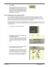
To configure multiple axes to use the error output, repeat this step for the other axes.
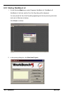
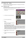
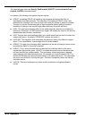
If youareusing adigital
output, drag the bright
blue OUT icon to the
grey Drive Enable OP
axis icon on the right of
the screen.
To configure multiple
axes with the same drive enable output, repeat this step for the other axes.
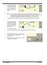
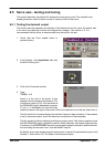
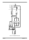
5. Click Apply at the bottom of the screen. This
sends the output configuration to the
NextMove ES.
See section 6.10 for details about saving
configuration parameters.