


5-18 Input / Output MN1928
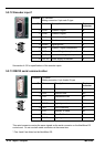
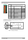
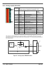
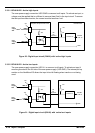
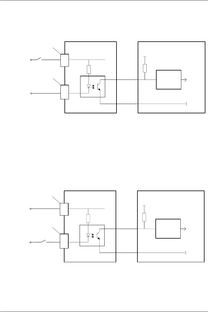
5.3.5.1 BPL010-502 - Active high inputs
The user power supply connection USR GND is common to all inputs. To activate an input, a
voltage must be applied that is sufficient to cause at least 5mA in the input circuit. To ensure
that an input becomes inactive, the current must be less than 1mA.
GND
MintMT
INX.16
+5V
NextMove ES
Back plane & opto-isolator card
8
96
pin
connector
‘X6’
10k
74AHCT14
2k2
TLP521-4
DIN16
1
‘X6’
User
supply
24V
User
supply
GND
USR GND
Figure 20 - Digital input circuit (DIN16) with ‘active high’ inputs
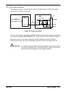
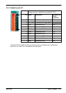
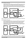
5.3.5.2 BPL010-503 - Active low inputs
The user power supply connection USR V+ is common to all inputs. To activate an input it
must be grounded to the 0V side of the user power supply (USR GND). The internal pull-up
resistor on the NextMove ES allows the input to be left floating when inactive or not being
used.
DIN16
GND
MintMT
INX.16
+5V
NextMove ES
Back plane & opto-isolator card
1
96
pin
connector
‘X6’
10k
74AHCT14
2k2
TLP521-4
USR V+
6
‘X6’
User
supply
24V
User
supply
GND
Figure 21 - Digital input circuit (DIN16) with ‘active low’ inputs