


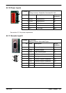
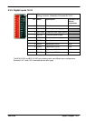
Input / Output 5-13MN1928
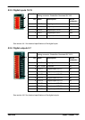
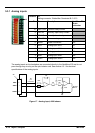
5.3.1.1 Error relay connections
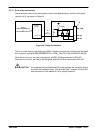
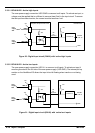
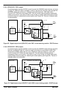
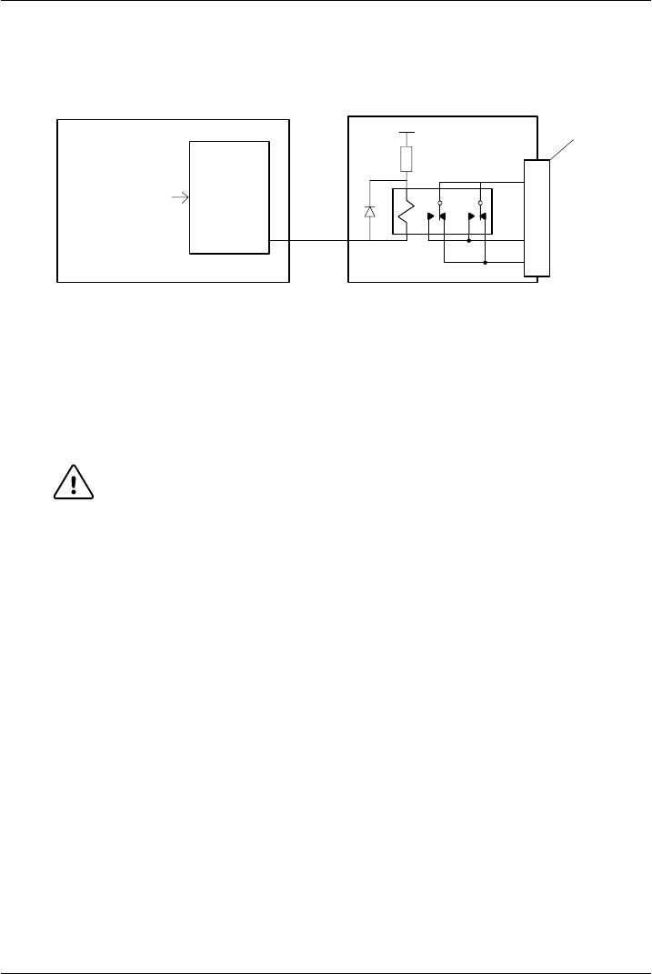
The double-pole relay on the opto-isolator card is controlled directly by the Error Out signal
(section 4.4.3), as shown in Figure 18.
Relay
NextMove ES
REL COM
REL NC
REL NO
96
pin
connector
Backplane
7
9
‘X8’
8
MintMT
GLOBALERROROUTPUT
or
DRIVEENABLEOUTPUT
+5V
Control
circuitry
Error Out
Figure 18 - Relay c onne ctions
The error output can be controlled by the RELAY keyword, and can be configured as the global
error output by setting GLOBALERROROUTPUT to 1000 (_RELAY0). See the Mint MT help file.
While there is no error , the relay is energized, and REL COM is connected to REL NO.
When an error occurs, the relay is de-energized, and REL COM is connected to REL NC.
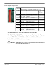
CAUTION: It is important that the NextMove ES jumper settings are correct to allow it
to control the backplane relay. JP4 must be fitted. Jumpers JP3 and JP5
must be removed. See section 4.4.3 for jumper locations.