


Input / Output 5-19MN1928
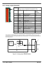
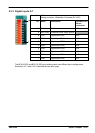
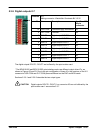
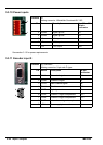
5.3.6 Digital outputs 0-7
Location X11
Mating connector: Weidmüller Omnimate BL 3.5/10
Pin Name Description NextMove ES
96-pin
connector
10 USR COM C ommon supply connection* a3
9 OUT COM Common* a4
8 DOUT7 Digital output DOUT7 b4
7 DOUT6 Digital output DOUT6 c4
6 DOUT5 Digital output DOUT5 a5
5 DOUT4 Digital output DOUT4 b5
4 DOUT3 Digital output DOUT3 c5
3 DOUT2 Digital output DOUT2 a6
2 DOUT1 Digital output DOUT1 b6
1 DOUT0 Digital output DOUT0 c6
The digital outputs DOUT0 - DOUT7 are buffered by the opto-isolator card.
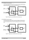
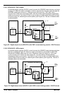
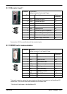
* The BPL010-502 and BPL010-503 opto-isolating cards use dif ferent output driver ICs, as
shown in Figures 22 and 23. Due to the pin configuration of these ICs, the functions of the X11
connector’s USR COM and OUT COM pins are different on the PNP and NPN cards.
Sections 5.3.6.1 and 5.3.6.2 describe the two output types.
CAUTION: Digital outputs DOUT8 - DOUT11 on connector X5 are not buf fered by the
opto-isolator card - see section 5.3.7.
1
10