


Operation 6-7MN1928
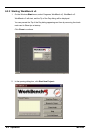
5. Click Apply.
This immediately sets the scaling factor f or
the selected axis, which will remain in the
NextMove ES until another scale is defined
or power is removed from the NextMove ES.
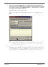
See section 6.10 for details about saving
configuration parameters.
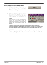
6.3.2 Setting the drive enable output
A drive enable output allows NextMove ES to enable the external drive amplifier to allow
motion, or disable it in the event of an error. Each axis can be configured with its own drive
enable output, or can share an output with other axes. If an output is shared, an error on any
of the axes sharing the output will cause all of them to be disabled.
The drive enable output can either be a digital output or the error output (see section 4.4.3). If
the NextMove ES is connected to a Baldor backplane with opto-isolating card, the error output
controls the relay .
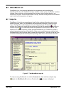
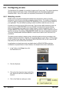
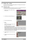
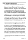
1. In the Toolbox, click the Digital I/O icon.
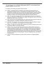
2. At the bottom of the Digital I/O screen, click
the Digital Outputs tab.
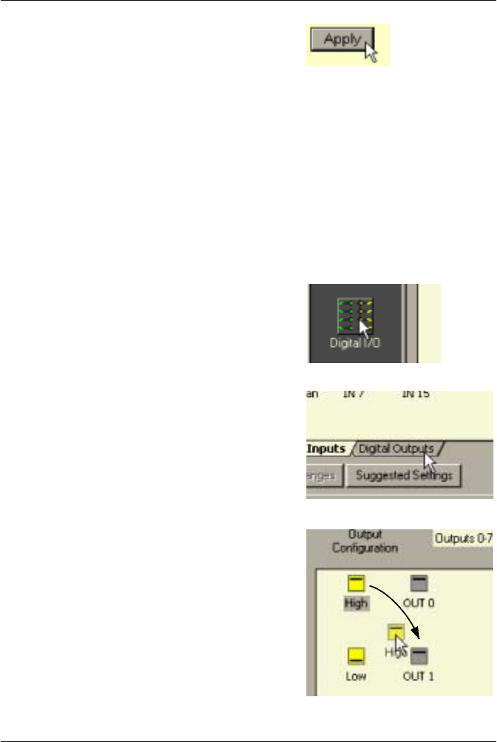
The left of the screen shows yellow High and
Low icons. These describe how the out put
should behave when activated (to enable the
axis).
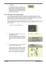
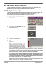
3. If you a re goingto use theerror output,ignore
this step and go straight to step 4.
If you are going to use a digital output, drag
the appropriate yellow icon to the grey OUT
icon that will be used as the drive enable
output. In this example, OUT1 is being used.
The icon’s color will change to bright blue.