


6-16 Operation MN1928
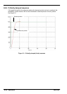
6.6 Servo axis - tuning for current control
6.6.1 Selecting servo loop gains
All servo loop parameters default to zero, meaning that the demand output will be zero at
power up. Most servo amplifiers can be set to current (torque) control mode or velocity control
mode; check that the servo amplifier will operate in the correct mode. The procedure for
setting system gains differs slightly for each. To tune an axis for velocity control, go straight to
section 6.8. It is recommended that the system is initially tested and tuned with the motor shaft
disconnected from other machinery. Confirm that the encoder feedback signals from the
motor or servo amplifier have been connected, and that a positive demand causes a positive
feedback signal.
Note: The method explained in this section should allow you to gain good control of the
motor, but will not necessarily provide the optimum response without further
fine-tuning. Unavoidably, this requires a good understanding of the effect of the
gain terms.
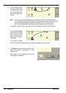
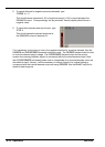
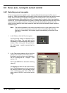
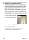
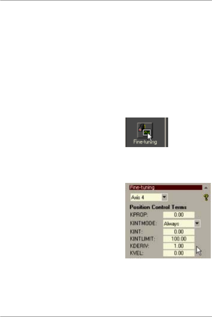
1. In the Toolbox, click the Fine-tuning icon.
The Fine-tuning window is displayed at the
right of the screen. The main area of the
WorkBench v5 window displays the Capture
window. When tuning tests are performed,
this will display a graph representing the
response.
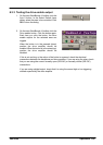
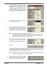
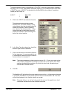
2. In the Fine-tuning window, click in the Axis
selection box at the top and select Axis 4.
By default, axis 4 is a servo axis (although it
can be reconfigured as a stepper - see
section A.1).
Click in the KDERIV box and enter a starting
value of 1.
Click Apply and then turn the motor shaft by
hand. Repeat this process, slowly increasing
the value of KDERIV until you begin to feel
some resistance in the motor shaft. The
exact value of K DERIV is not critical at this
stage.