


Appendix A-1MN1928
A.1 Axis renumbering
The factory preset axis numbering assigns axes 0 - 3 as stepper axes and axes 4 and 5 as
servo axes. However , it is possible to alter the axis numbering scheme. For example, you
might wish axes 0 and 1 to refer to the servo axes, and axes 2 to 5 to refer to the stepper
axes. There are certain hardware limitations that must be considered when altering the axis
numbering scheme:
H A maximum of two servo axes and 4 stepper axes may be assigned.
H Axes 0 and 4 share an internal hardware channel. This means they cannot both be servo
or stepper axes. If one is servo, the other must be stepper. The servo demand output for
axis 0 or 4 is always the DEMAND0 output, with Encoder0 as the feedback channel.
The stepper output is always STEP0.
H Axes 1 and 5 share an internal hardware channel. This means they cannot both be servo
or stepper axes. If one is servo, the other must be stepper. The servo demand output for
axis 1 or 5 is always the DEMAND1 output, with Encoder1 as the feedback channel. The
stepper output is always STEP1.
H Axes 2 and 3 are always stepper axes; they cannot be reassigned as servo axes.
Their outputs are STEP2 and STEP3 respectively.
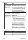
Before axes can be reassigned, they must be turned of f. This removes their existing servo /
stepper assignments and inhibits their electrical outputs. In the following example, axis 4 will
be reassigned as a stepper axis, and axis 0 as a servo axis:
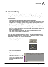
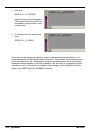
1. In the Toolbox, click Application, then
click the Edit & Debug icon.
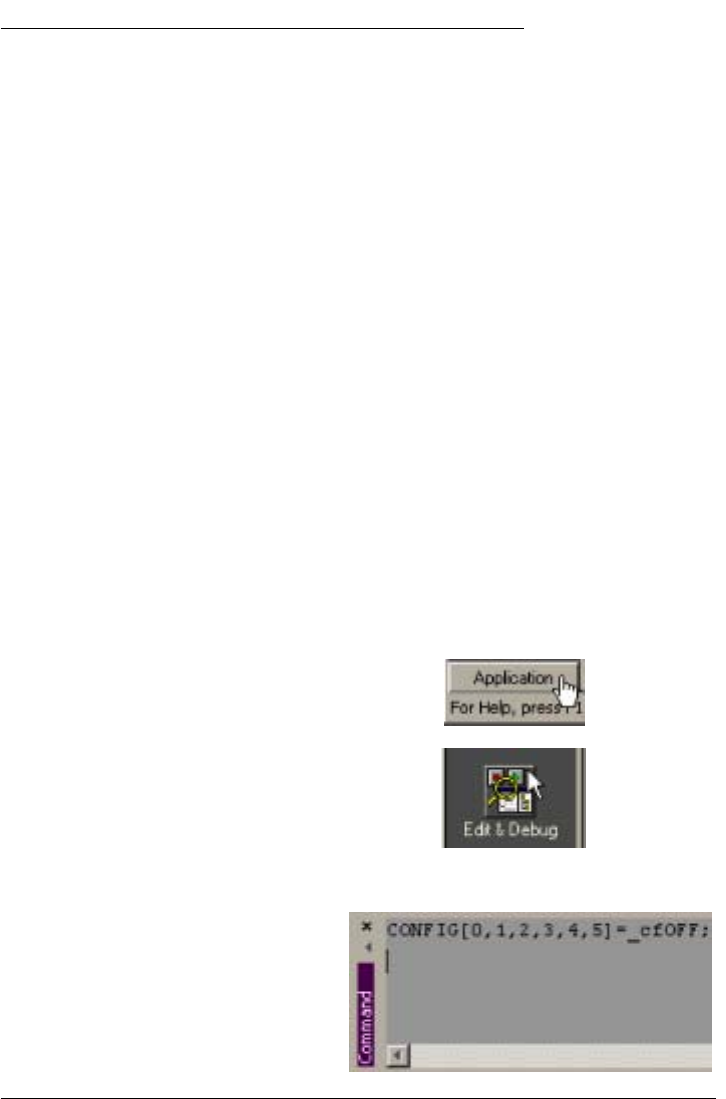
2. Click in the Command window .
3. Type the command:
CONFIG[0,1,2,3,4,5]=_cfOFF;
This will turn off all axes. There will
now be no electrical output for any of
the axes.
A Appendix
A